

Preamble
The local classic car sales garage put me onto the 123 Ignition system some time ago. I hadn’t heard of them when I was rebuilding LGL but they were fitting them to all the vehicles that crossed their books with few issues. Easy to install, set up and maintenance free. They are available for 26 models of classic cars, so there’s something for everyone… even DAF!
I had originally replaced the Lucas D25 distributor with an electronic unit from Accuspark. It had its quirks (poor advance, retard tuning being one of them) but as a whole it worked fine and I was happy not to have to worry about burnt contact breakers etc (I’ve never had much luck with such things).
However, a chronic misfire and idle issue had started to occur earlier this year instilling a lack of confidence during the infrequent journeys I make. The normal troubleshooting for such things didn’t help.
I toyed with the idea of having the oringal Lucas D25 restored with electronic ignition but I noticed the body was actually cracked so there was little point.
The Parts
123 Ignition offer 3 flavours of ignition: Switch, Tune and Tune+.
“Switch” offering 16 different selectable ignition curves. This is the unit I have installed. The exact model name: GB-4-R-V-POS
“Tune” allowing the user to build there own ignition curve from two sets of data (static and advanced) this is handy if you need a distributor for a highly modified engine such as a vehicle used on the track.
“Tune+” is fully wireless and ignition curves are designed from scratch on an app and can be adjusted on the fly via Bluetooth. The app has a dashboard display providing, RPM, speed, voltage and temperatures and pressures of this and that. There’s even a Bluetooth immobiliser function.
The temptation of the Tune+ is obvious especially with the Bluetooth immobiliser function. But there were too many “what if” scenarios bouncing around in my head… imagine dropping your phone in the lake!
The simplicity of the “Switch” makes perfect sense for a simple vehicle.
Installation
The instructions to install the new “Switch” unit as super simple and clear. They go into sufficient detail. Not all of which I will repeat here.
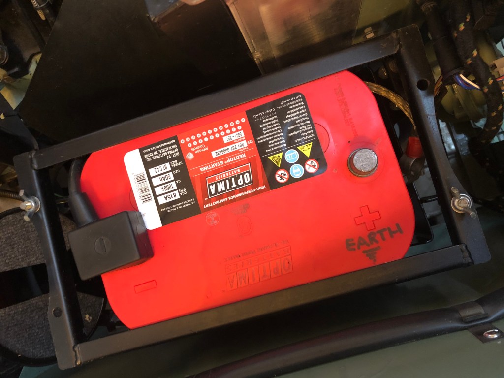
First, disconnect the battery.
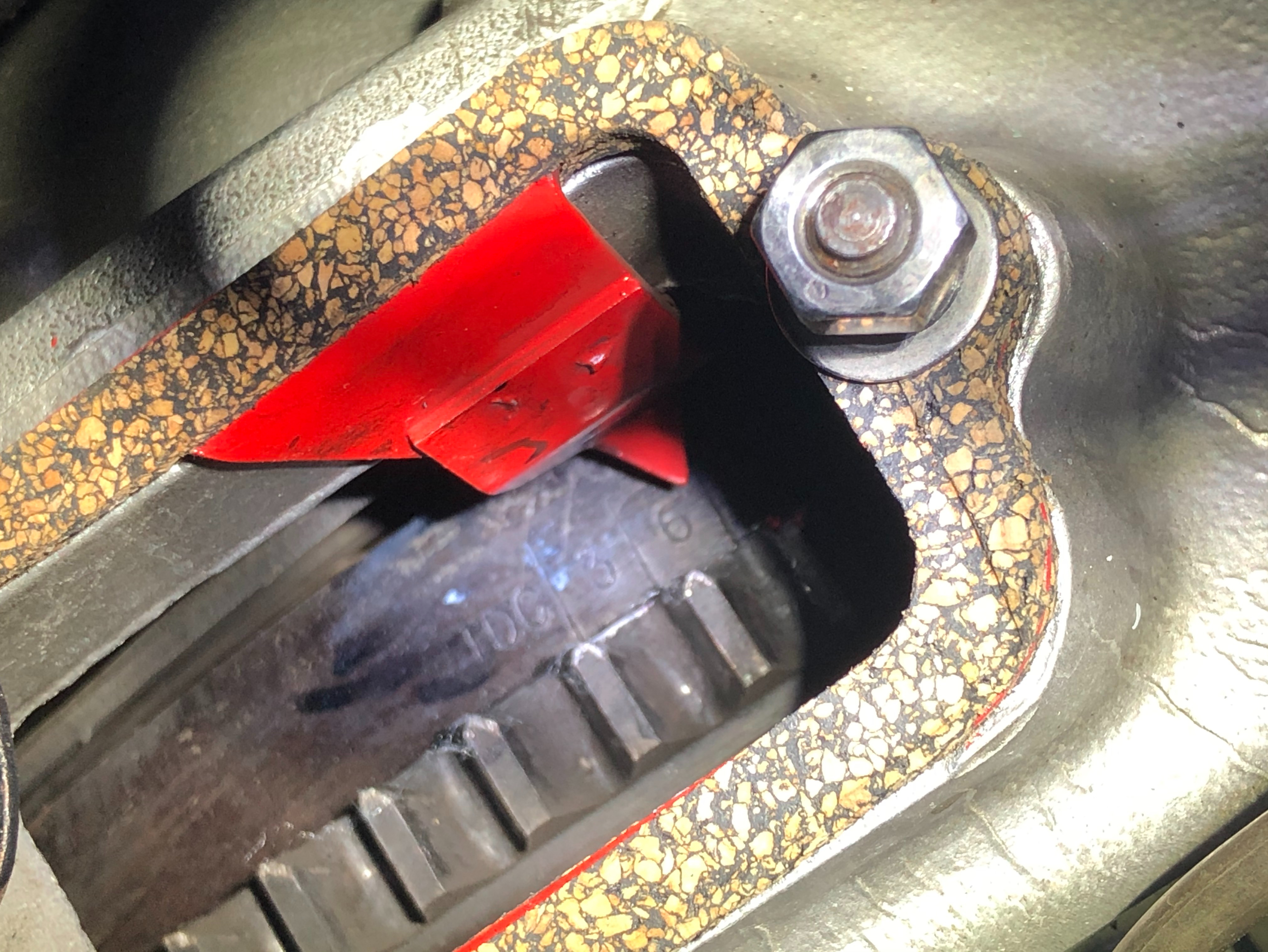
Next, ensure the rotor arm of the original distributor is pointing towards Cylinder No 1 (the one nearest the radiator)and the timing mark on the flywheel (or front pulley, depending on model) is roughly on the mark required.
For LGL, running on 98 Octane petrol this is 6 degrees Below Top Dead Centre (BTDC). This will give a reference point when setting up the 123 Ignition unit. (I’m not worrying about the presence of ethanol in modern petrol and its effect on ignition timing for this installation)
I find the easiest way to do find and align the mark on the flywheel is to remove the spark plugs and turn the engine with the hand crank until the correct position is obtained. (Removing the plugs will eliminate having to work against the cylinder pressure when turning the engine over by hand. It may add some backlash but this would be minimal)

Accuspark distributor… (vacuum advance already disconnected) 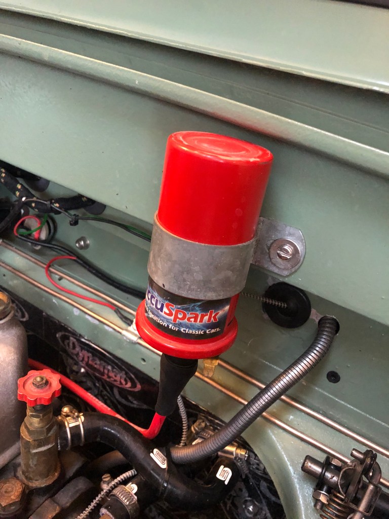
… and coil
It’s recommended to use a 3.2 ohm coil with the new distributor. I’d rather not take the chance the misfire was caused by the old coil so a new Bosch unit was installed.

New ignition system 
Bosch 12v, 3.2 Ohm coil
Next the old Accuspark unit is removed and reverently packed away.

Wiring is disconnected 
Pinch bolt at the base of the distributor is loosened right off

Distributor is removed from the engine block 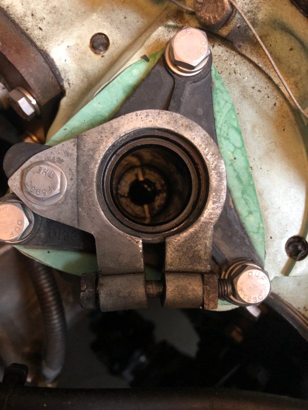
Ready for new 123 Ignition (and a good clean up around the work area)
Side by side the two units look quite different. The “Switch” distributor has no counterweights in the bottom as all timing is purely electronic.
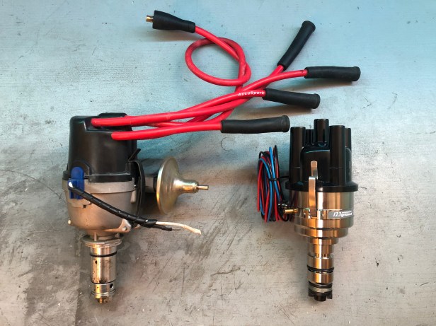

Internals of the Accuspark 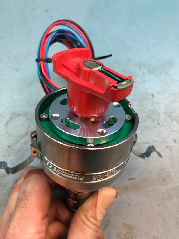
Internals of the “Switch”… not that there’s much to see
The timing and advance retard in the “Switch” is fully electronic, hence the lack of advance unit on the new unit. There is still a need for a vacuum pipe for the carburettor and this is accommodated with a spigot on the other side of the distributor.

Now for the fun part…
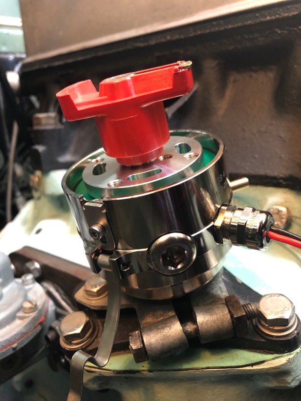

Wiring is connected and tidied up with some cable wrap 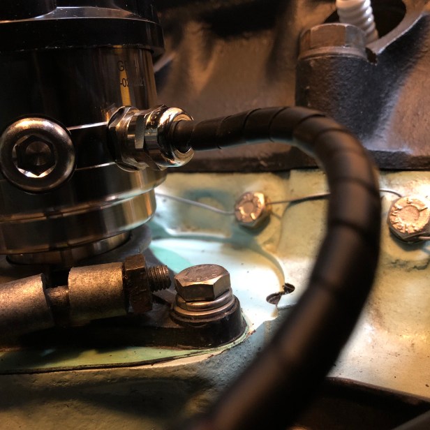
Much tidier than loose wires everywhere
I don’t have any photos of the final set up as I was still suffering with acute dizziness at the time. It was enough working on the vehicle let alone getting decent shots.
The instructions cover line by line what needs to be done and the LED queue lamps makes it super easy.
There’s an additional wire on the “Switch” taking a feed direct from the ignition switch to power the electronics in the unit.

With the low voltage wires connected, new HT leads were made. The old ones would have been too short, give the new unit is slightly shorter in stature.

New kit of parts from Accuspark. A 2m length was sufficient for 4 leads and the feed from the coil with some to spare.
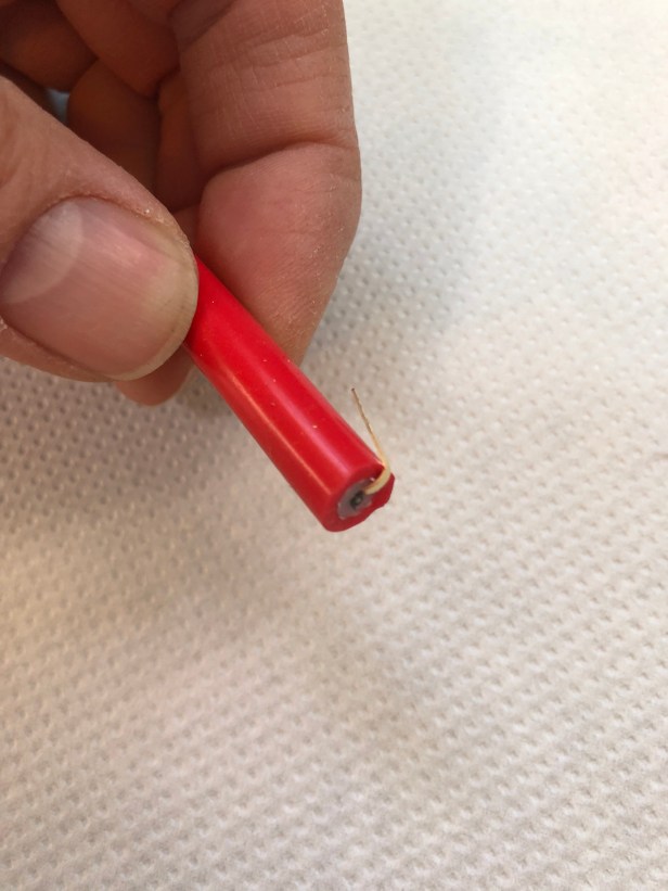
First the brass tang is pushed into the end of the lead. This transmits the current from the carbon core to the connector 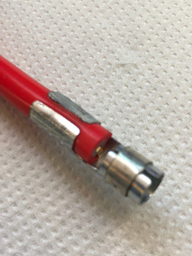
Then the connector is crimped firmly in place. Ensure the tang is opposite the crimps (this is a spark plug connector) 
At the distributor end of the cable an angled connector is used. 
Repeat 4 times 
Remember the firing order when making leads. (1,3,4,2)
Curve Settings
To be honest, I struggled finding an optimal setting. The “Switch” is a replacement for most British 4 cylinder engined cars (one size fits all kind of thing) and although comprehensive ignition curve data is provided in the installation manual, I don’t know what it’s telling me and Land Rover have never published ignition curve data to measure it against.
As I don’t use the vehicle that much, working my way through each of the 16 settings would take an age and possible not do the engine much good.
I emailed 123 Ignition for guidance.. and their advice for the low compression Land Rover 2.25 petrol engine is curve “7” or “b”.
Closing Comments
That’s the unit installed. Pretty simple although it took near 3 weeks given the condition I’ve had. But it wasn’t time to start the engine just yet. I was also working on an SU Carb conversion 🙂
More on that in the next post.

Dear Little Green Landy
Morning and thank you very much, a lot of starting issues from one day to another in my Rand Lovet as says my kids when they are little, only Series Land N° 6 (3 Santana) and one 1976 Range Rover, Accuspark distributor arrive tomorrow at home.
My first motor car at 17 years old was a 1956 Series I, Landy.
All the Best
George Jarry
LikeLike
Hi Georg, thanks for leaving a message. The Accuspark is a great upgrade. Sounds like you have some experience with keeping Rand Lovets on the road. All the best. Andy.
LikeLike