
Brake lines
Preamble
2 new brake lines needed to be made. One from the master cycling to the servo. Another from the servo to the 5 way splitter. The clutch line needed a bit of strategic adjustment but that was easy enough with a pipe bender.
The kit came with two finished lengths of 3/16″ copper pipe but neither was long enough to run across the top of the bulkhead. The rest of the hydraulic lines in LGL are made from copper / nickel. As there is a distinct visual difference, a long role of the stuff was ordered from Vehicle Wiring Products in the UK. Copper / nickel is a little more resistant to work hardening (than copper) and flares easily. It also has a higher tensile strength and burst pressure.
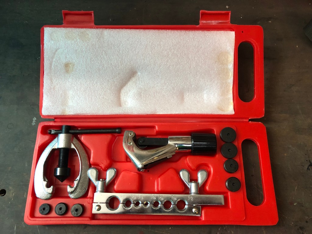
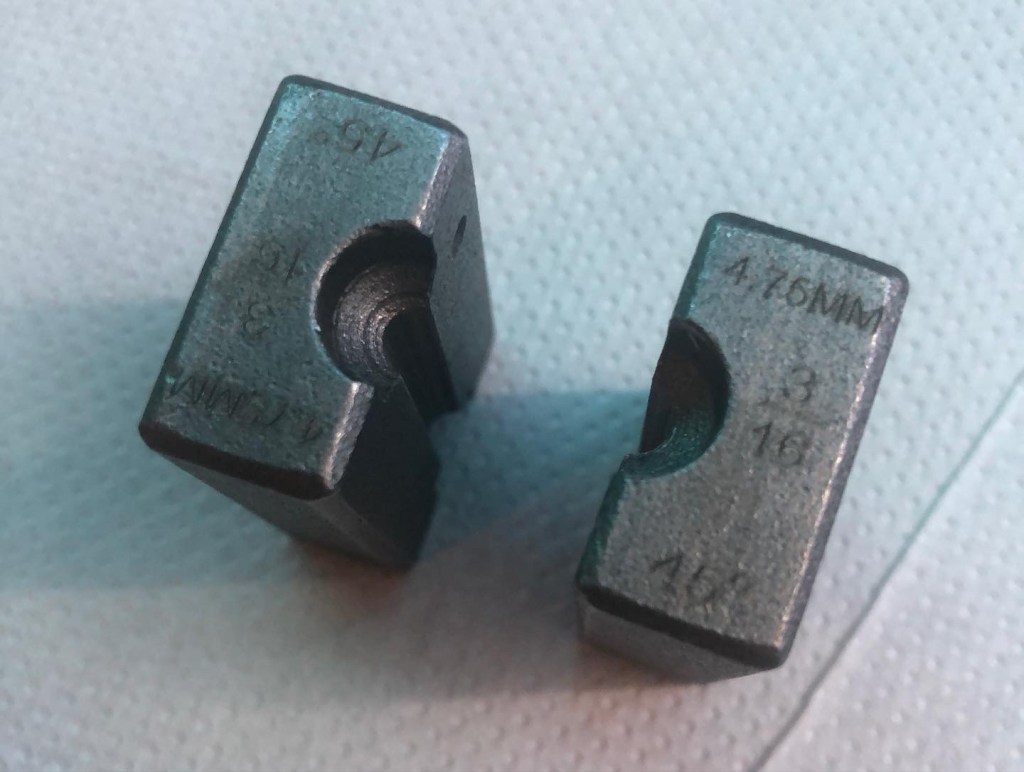
To make off the ends of the new lines, I needed a brake pipe flaring kit… The first I ordered was utter garbage and was sent back. It was impossible to make the ends off safely.
The second kit was aimed at commercial users, was far better quality and had the correct, hardened steel dies for SAE and DIN flares. Land Rover use an SAE flare.
You get what you pay for…

Procedure
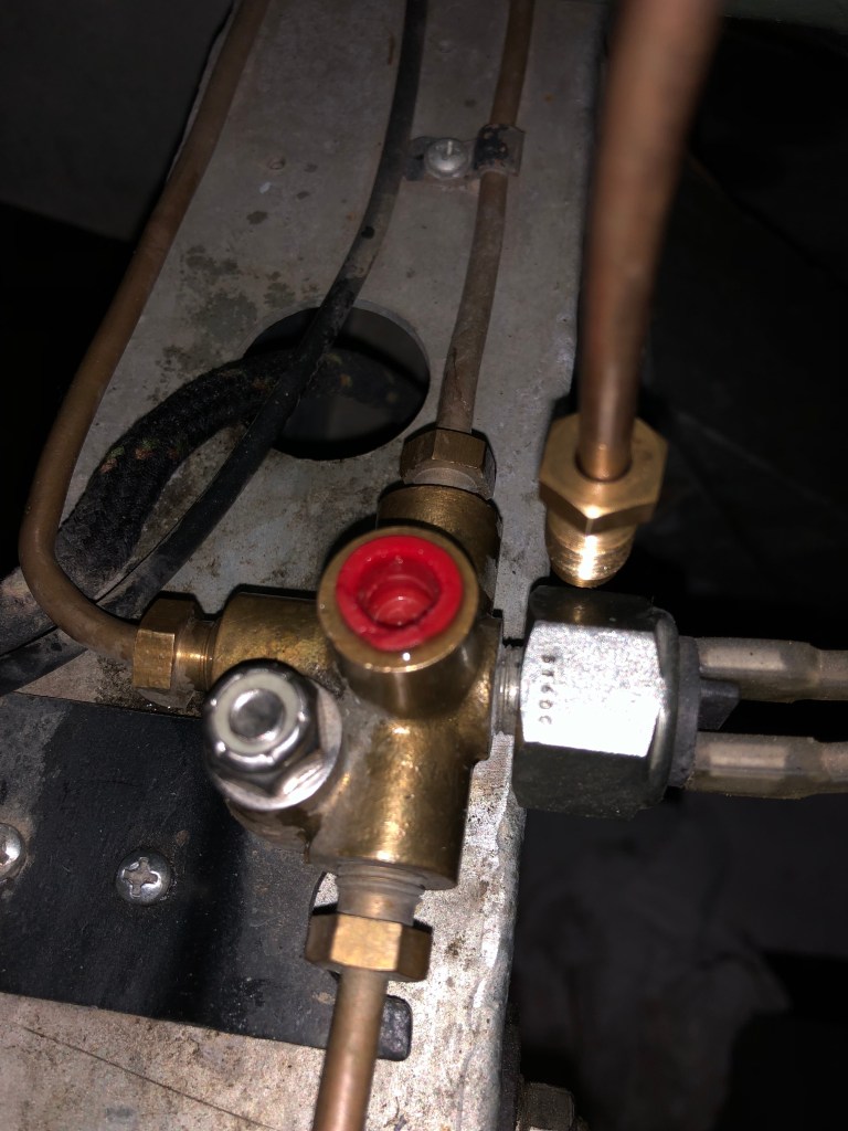
- Thoroughly clean the 5 way split block with a brass wire brush
- Disconnect and drain clutch line from flexible hose
- Disconnect and drain brake line up to the 5 way splitter (cap off the orifice to keep dirt out of the brake system)
- Mark out pipe runs on the bulkhead
- Form new line from brake master to servo
- Form new line from servo to 5 way splitter
- Install lines and clip to bulkhead
- Bleed clutch and brake system
First the clutch is disconnected and drained.

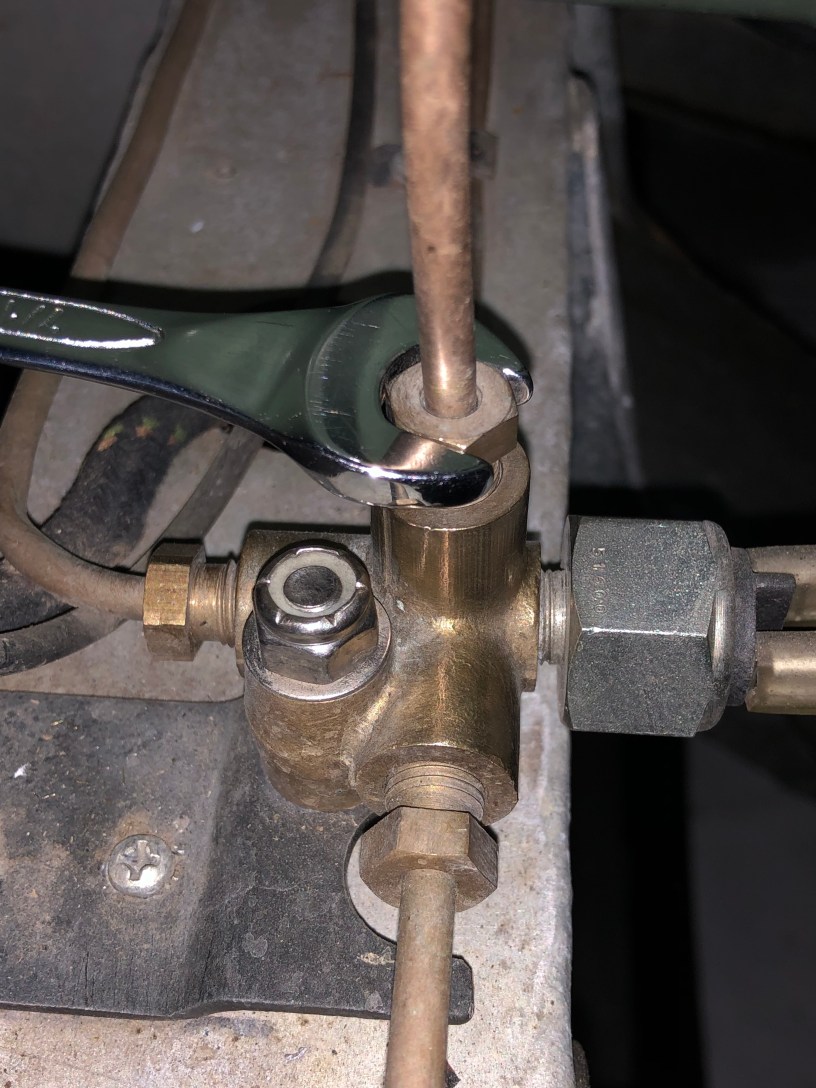
Then the main brake line is disconnect, drained and removed from the bulkhead. I kept it just in case there’s a need to return the system to original.
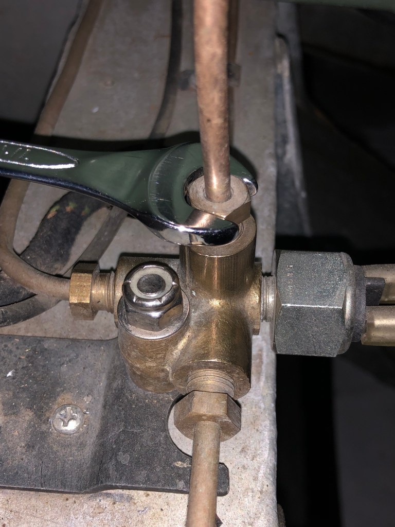
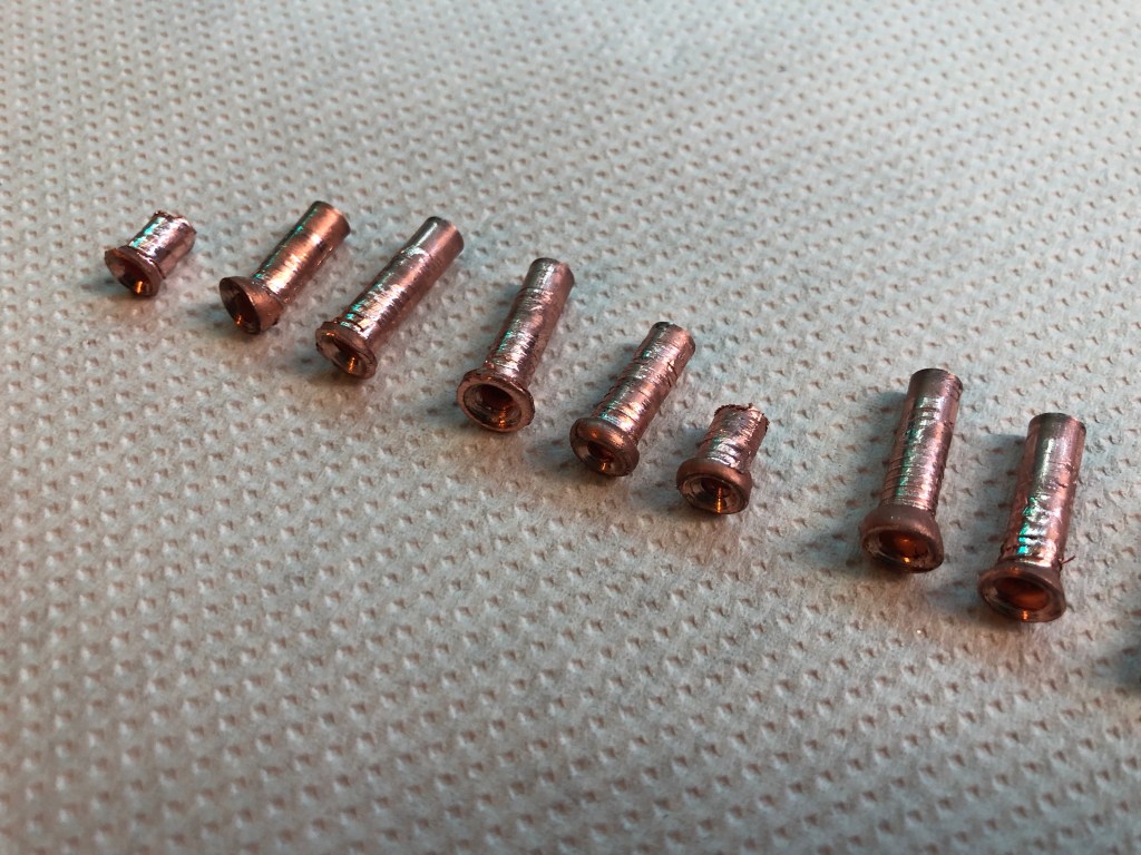
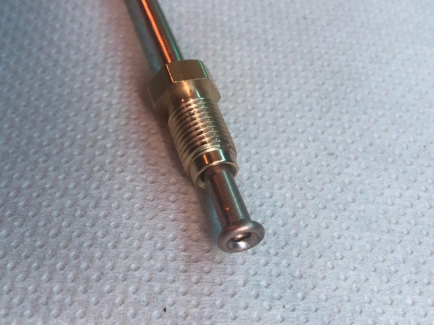
I didn’t take many photos of making the new brake line. I’ll do a seperate post on pipe flaring at a later date though. Using the new tool was very simple. The 3/16″ die made superb ends, and after much marking out and measuring, a new brake line emerged.
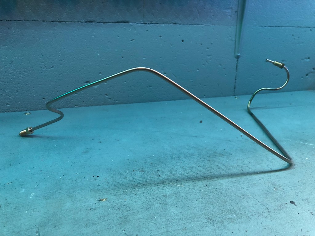
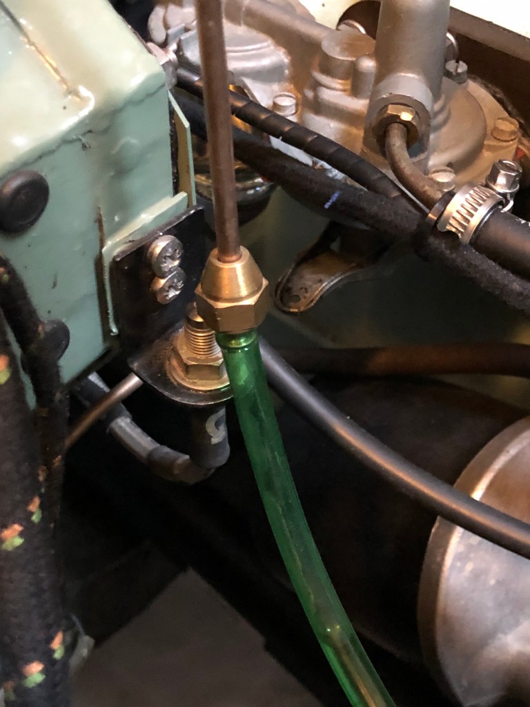
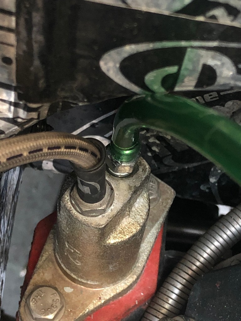
At this point all the new brake lines are connected to and from the servo. The only thing that needs to be done is to bleed the system (as well as the clutch).
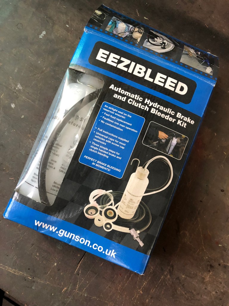
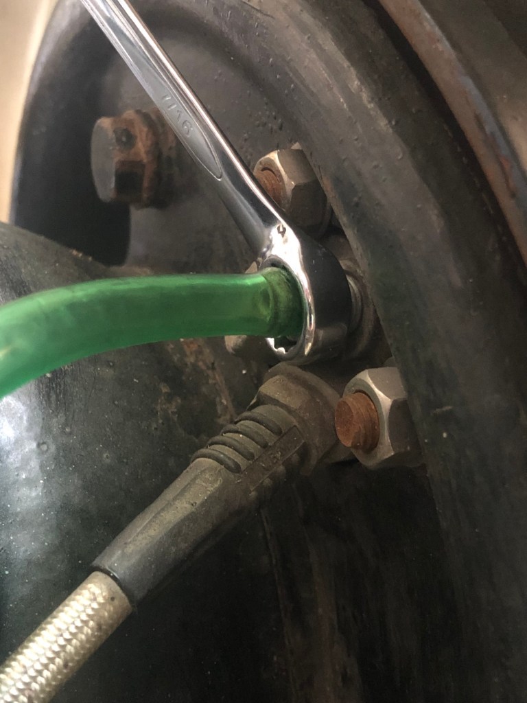
I use an Eezibleed kit. This uses the air pressure in the spare tyre to push the fluid in the reservoir through the system when the bleed screw is opened at each cylinder. From experience, I’ve found it’s important to air down the spare tyre to about 20 psi. Higher pressure seem to introduce a lot more air bubbles into the system…. turbulence?? cavitation??
Always start with the wheel cylinder furthest away from the master.
The servo is now installed and plumbed in. Next will be a quick one, to install the vacuum supply and refit the wing.
