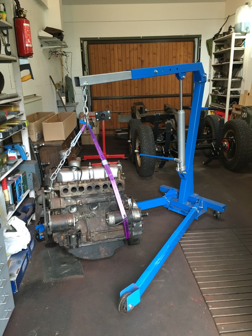
Time to get dirty again. With a good deal of the small parts now reconditioned (or awaiting replacement parts to finish the job) thought has turned to the engine.
Turner Engineering form the UK are world leaders in remanufacturing Land Rover engines and the will do the rebuild. I’m not a big fan of engine rebuilds, I’ve done a couple of motorbike engines and found, it’s very easy to do a bad job.
Turner offer an exchange programme, whereby they send you a new engine and the courier takes your old one back for remanufacturing and so on. The downside is that LGL would end up with a non original engine. So we’ll see.
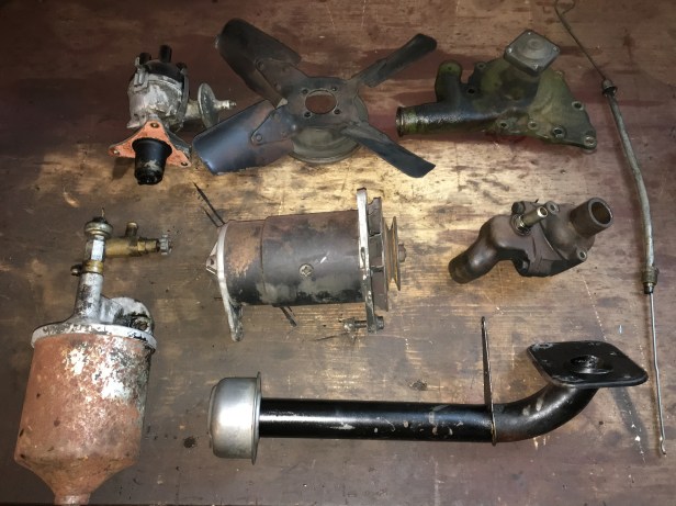
But whatever happens, the engine will be exchanged in a”stripped” state, this mean removal of, clutch, flywheel, flywheel housing, starter motor, dynamo, fuel pump and filter, distributor, water pump, fan.. well everything that isn’t the block, cylinder head and timing case.
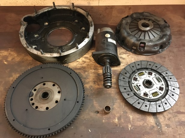
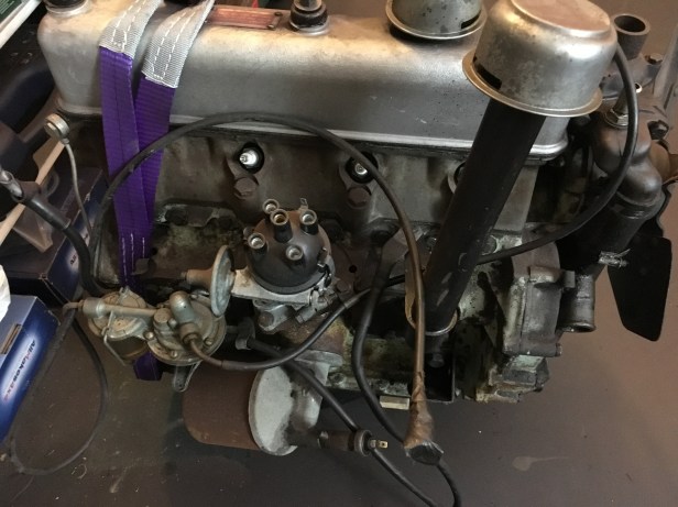
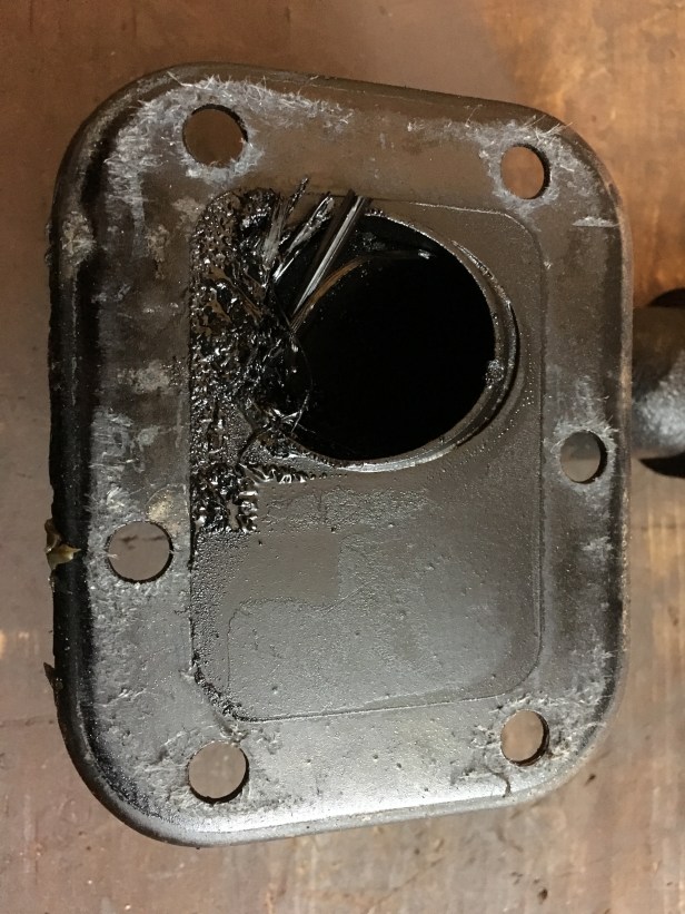
A gearbox would normally fix to these 12 studs. Clutch in the middle is the first to come offClutch off and you can see the friction face on the flywheel. The device with the heavy spring is the starter motorStarter motor and flywheel off revealing the inside of the flywheel housing. Clearly the crank shaft (the end of which is the plate with the 8 holes) seal is leaking. The flywheel housing is fixed with 8 bolts, 6 of which (1,2,3 and 9,10,11 o’clock) can be see embedded in the accumulated gloopFly wheel housing removed to reveal the genuine colour of the cast iron blockThis ring of teeth will need to be replaced. Curiously the toothed “ring” and flywheel are two separate parts and mate together purely by an “interference fit”…i.e, they fit together so tightly, they won’t move against each other. To get the ring off, is simple… a sharp blow with a good chisel between the teeth and it breaks. Refitting a new one is harder. The flywheel needs to be cooled in the freezer for couple of days, and the new ring heated in the oven for an hour or so, then the two should slot together. Well thats the theory, I’ll let you know if it works.Flywheel housing, flywheel, clutch pressure plate, clutch friction plate, starter motor and main shaft bushWith the flywheel assembly off, time to remove the remaining ancillaries Water pumpValve cover removed revealing (not unexpectedly) the valve train 🙂This is the bottom end of the oil filler tube. Quite how this much grass got down there is a mystery. Not sure how the engine would have liked it. Composting engine??From bottom left, clockwise: Oil filer assembly, heater tap (the small brass thing), Distributor, Cooling fan, Water pump, Thermostat housing, Oil filler pipe, Dynamo… and on the far right, the dip stickOne stripped engine…. but it obviously can’t go in the post like this….. To be continued