

With the chassis and engine gone, there’s a lot more space in the garage, so time for a bit more of a tidy up and start stripping the gearbox down.
The Series gearbox didn’t evolve much between 1948 and 1971 but there were some notable milestones along the way.
Early Series 1 gearboxes saw common failures in the mail shafts, chipped teeth and damage to second gear (due to lack of syncro between 1st and 2nd). These were exacerbated with the introduction of a larger engine in 1958.
1961 saw the internals reworked to better accommodate the increased power of the 2.25L and (later) the 2.6L engines. By 1971, the gearbox was fully synchronise and had a completely redesign of the clutch release mechanism.
The gearbox in LGL is a suffix D unit and comprises the following:
- 8 forward gears, 2 reverse.
- No synchro between 1st and 2nd (double clutching is required to make a smooth gear change)
- Synchro between 3rd and 4th gear
- Has the earlier (considered more robust) clutch release mechanism.
All this is housed in 2 gear boxes. The Main Box and Transfer Box.
The gearbox didn’t sound all that bad on the short period I was using the vehicle before the rebuild started but I am assuming to have to replace most of the gears. All bearings, seals and gaskets will be replaced
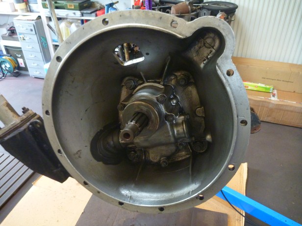
Bell housing removal
I made the mistake whilst rebuilding a Series 3 gearbox, of first removing the handbrake assembly (on the rear output shaft), this meant there was no way to lock the gearbox and prevent it rotating…. an essential point when needing to remove nuts on gear shafts; this time I “RTFM” 🙂
Step one is to remove the bell housing. This is where the gearbox mates with the engine and houses the clutch. The splined shaft in the centre engages with the crank at the back of the engine.
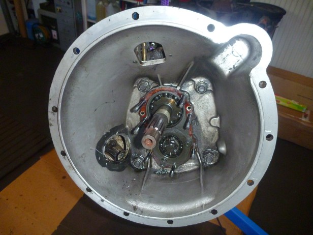

Clutch Release Mechanism
The more complicated of the two release mechanisms used in the Series land rover, it is considered the more robust.


How did you get the nut off the main shaft? I’m working on one and the nut is stubbornly stuck. I’m trying to chase it off with a large screwdriver.
LikeLike
Hi Teddy, I already had a home made tool that came with a Series 3 I had some years ago. You could try putting some heat into the nut with a blow lamp. Chasing it off might then be a bit easier. Good luck. Andi.
LikeLike
its a counter clockwise thread
LikeLike
Sorry… given the post you are respond too, I realize which nut you’re talking about. The one behind the clutch release housing? I don’t have the special tool for this one. I used a punch and hammer too. But remember it’s a left hand thread!
LikeLike
Hi im looking for the bush for withdrawal race sleeve do you know where I can find this part?
LikeLike
Hi Paulo,
Thanks for the message. The bush for the withdrawal race sleeve is part number 231075 and at time of writing this, is available from:
Craddocks: https://www.johncraddockltd.co.uk/search/results.html?s=231075
Hope this helps.
LikeLike