Finally all of gears have arrived. With the exception of the revers idler and the PTO pick off gear (which will be removed in time to accommodate an overdrive) all gears are new.
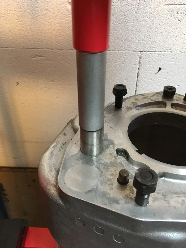
Coincidentally the new press I bought has also arrived. Found on Ricardo (Swiss version of eBay), it was cheap as chips and reasonably good quality. I now have 12 tons of press at my disposal, so without further ado……
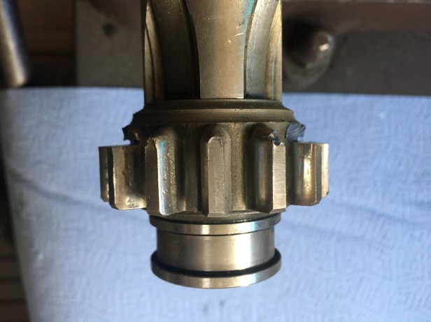
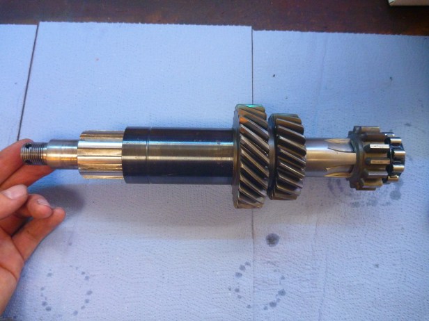
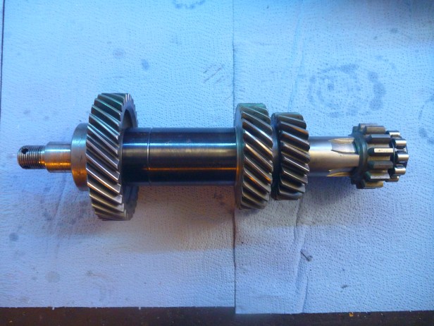
Layshaft:
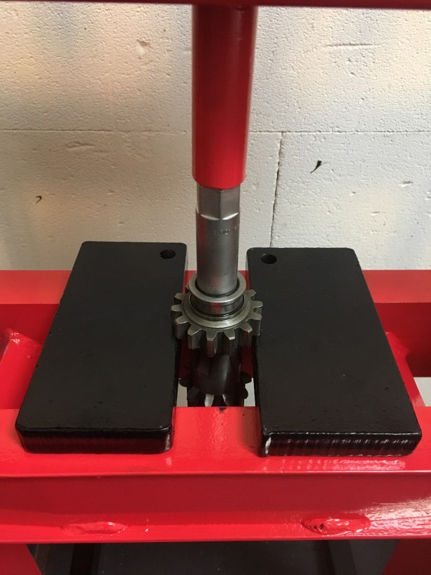
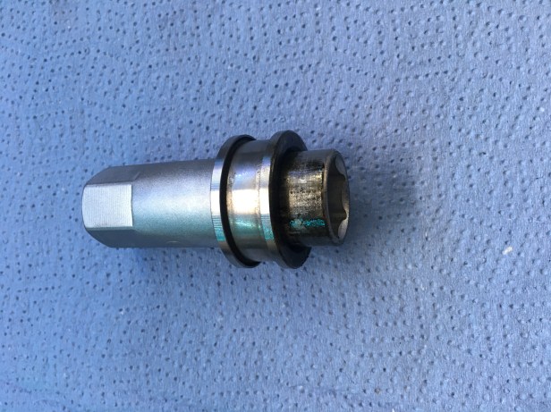
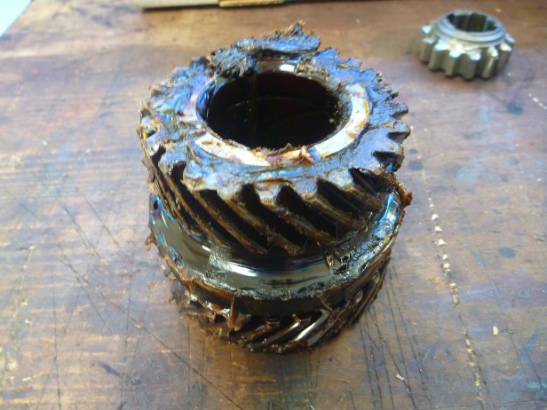
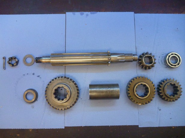
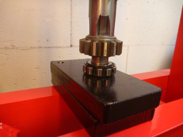
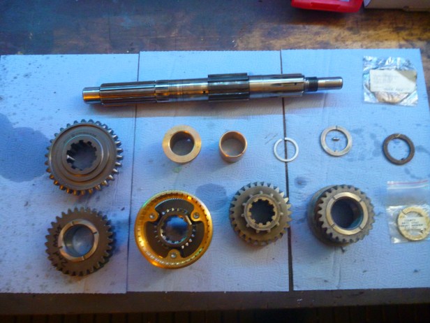
First gear and the old bearing shell need to be pressed off. But as the chamfer of the gear makes it very hard to hold the assembly in place some surgery needs to be performed…..Shoulders are cut into the teeth to provide a parallel surface to hold the shaft in the press. Shaft is then pressed out of the bearing shell and gear.Everything in place and ready to go. A suitably sized socket, matching the diameter of the shaft is used as a drift and pressure is applied….… then remove the bearing shell from the drift. Good job i had a press.Original Land Rover 3rd speed cluster, preserved in Marmite since 1962Pretty straight forward. From top left, clockwise: Split pin (used… yes, I know….tut tut), castleated nut, thrust washer, lay shaft, 1st speed layshaft gear, layshaft bearing, 2nd speed layshaft gear, 3rd speed layshaft gear, distance piece, layshaft constant gear, distance washer
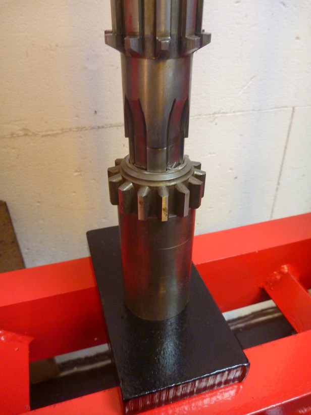
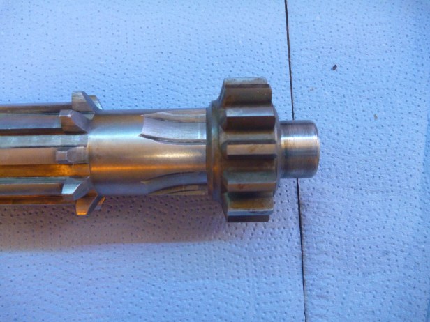
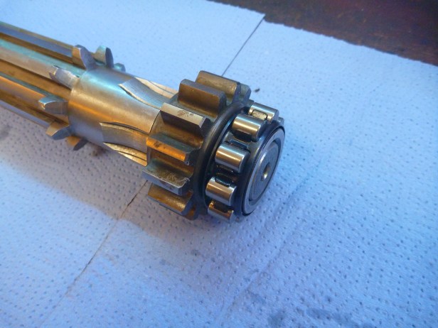
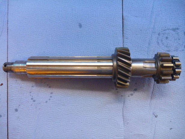
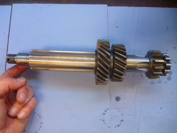
1st speed gear pressed onto the shaft… using the old shaft distance piece as a drift. You can see how tight the fit is, steel from the gear is “shaved” off as the two are driven together1st speed gear in placeLayshaft bearing being pressed onBearing needs to be flush with the face of the shaftAll of the components simply slip onto the shaft form here on in. 2nd speed layshaft gear in place……followed by 3rd speed…… then the new spacer piece… and finally the constant gear. Thrust washer, nut and pin will be fitted once installed into the bell housing.
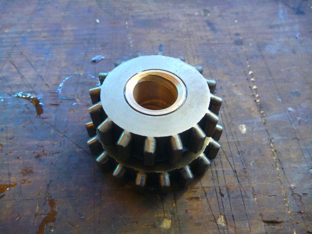
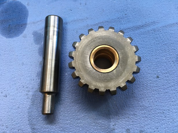
Reverse Gear:
New bronze bush pressed inShaft and gear ready for installationThe shaft is offered up from the outside of the box (thin end first)Shaft being pressed inShaft and reverse gear in place. Double and triple check the gear is the right way round on the shaft
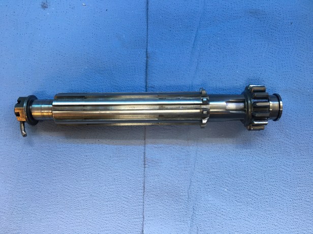
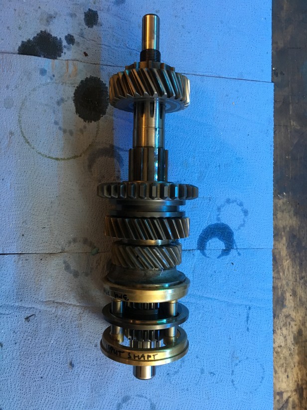
Main Shaft:
There is a little more work involved in putting the main shaft back together. Its important that the 2nd and 3rd speed gears have the correct tolerance set. Given all of the parts going back on the main shaft are new, I expected there to be a degree of “fettling” to ensure the correct tolerances were achieved. I won’t bore you with the technicalities but it transpired the tolerances between the thrust washer and gear face and thrust washer and spring ring were within the permitted tolerance…. between 4 and 7 thousandths of an inch. To measure such a small gap a set of feeler gauges is used.
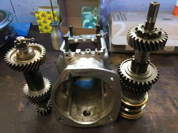
Top: Main shaft. From top left clockwise: 1st speed mainshaft gear, distance sleeve 1, distance sleeve 2, spring ring, thrust washer with distance sleeve peg, 3rd speed mainshaft gear, pick off gear, synchromesh unit, 2nd speed gear. Three round “washers” on the right are thrust washers but of varying thickness to establish the required tolerance As mentioned above, the mainshaft build was a little more involved and fiddly but this is the completed itemLeft to right: layshaft, main case, mainshaft
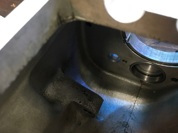
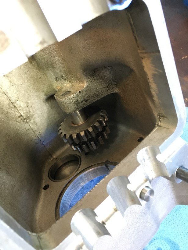
Main Case Build:
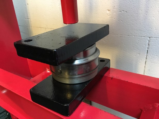
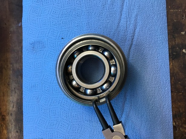
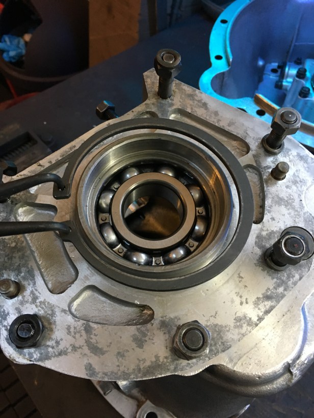
Mainshaft bearing, bearing housing and the two large circlips
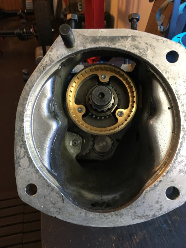
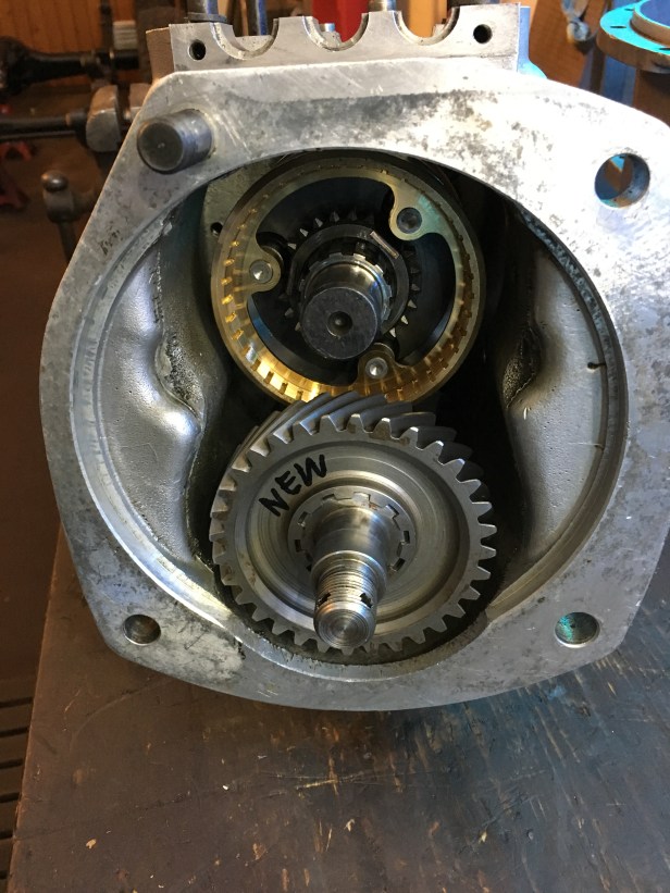
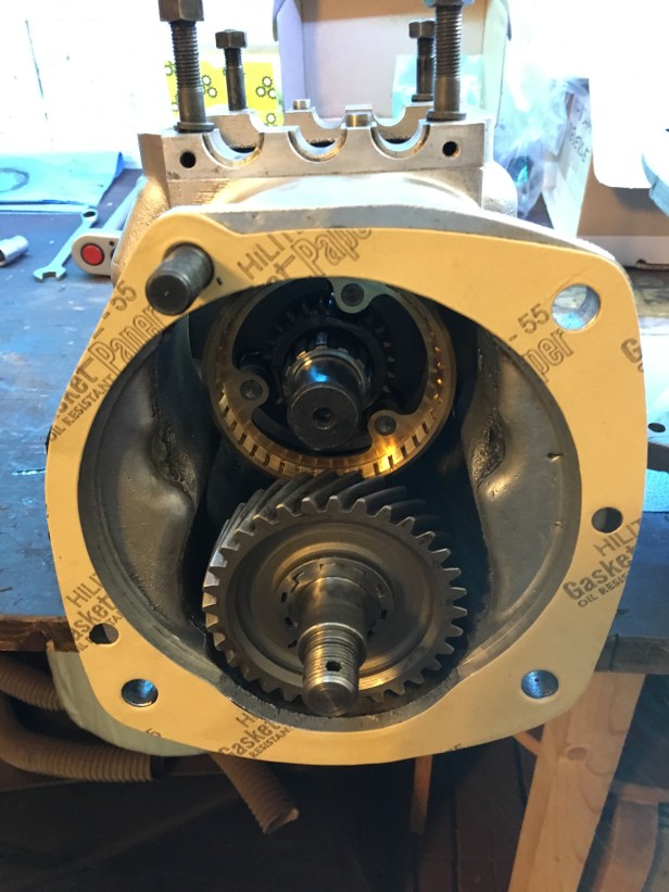
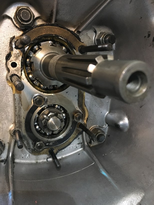
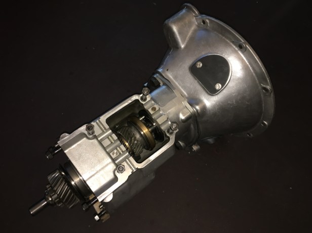
I love this thing…. Main bearing being pressed into the bearing housingCirclip piers are used to “compress” the circlip. Once released, it snaps into the groove on the inside of the bearing carrier, thus securing the bearing in placeThe bearing is pressed into the main case from the inside and secured with another circlip, this time the circlip must be “expanded” to fit over the groove on the bearing carrier Mainshaft installed. The shaft simply pushes through the mainshaft bearing (above)…. Triple check that the reverse gear is the corect way round on the shaft. The end of the layshaft will locate n the race at the back of the case. It takes a little fiddling about to get it in the correct location.Layshaft installed. The constant gear will engage with the primary pinion installed previously in the bell housingNew gasket in place. A bead of Loctite sealer was used on both faces (not pictured) to ensure an oil tight fitIn my infinite wisdom, I installed the clutch release mechanism without thinking I would need to fit the nut on the end of the layshaft. So this had to be removed, destroying the gasket in the process. A new 5 pence gasket is required. Here we see the layshaft thrust washer, castleated nut and split pin installed. This is obviously the inside of the bell housing, the 4 securing bolts can be seen at each corner.Mainbox and bell housing back together again. Next will be the transfer case rebuild
I have a 1961 Land Rover series II. I am doing a complete restoration. I’m into the transmission now, I’m a marine diesel mechanic with over 40 years of experience. I am having a issue with doing a total rebuild of the gear box. The engine is totally rebuilt. Should I even go after the gear box? I drove it for a couple of months before I started the overhaul.
Apologies for the delay. If the gearbox doesn’t have any loud rumblings or whines, then I’d be inclined to leave it alone. If the gearbox is out, then replacing the gear release bearings is a good idea and straightforwards. If you decide to do full rebuild, I would reuse the original gears, replace the bronze bushings and all the bearings with good quality ones… Timken or similar. Good luck.


I have a 1961 Land Rover series II. I am doing a complete restoration. I’m into the transmission now, I’m a marine diesel mechanic with over 40 years of experience. I am having a issue with doing a total rebuild of the gear box. The engine is totally rebuilt. Should I even go after the gear box? I drove it for a couple of months before I started the overhaul.
LikeLike
Apologies for the delay. If the gearbox doesn’t have any loud rumblings or whines, then I’d be inclined to leave it alone. If the gearbox is out, then replacing the gear release bearings is a good idea and straightforwards. If you decide to do full rebuild, I would reuse the original gears, replace the bronze bushings and all the bearings with good quality ones… Timken or similar. Good luck.
LikeLike