
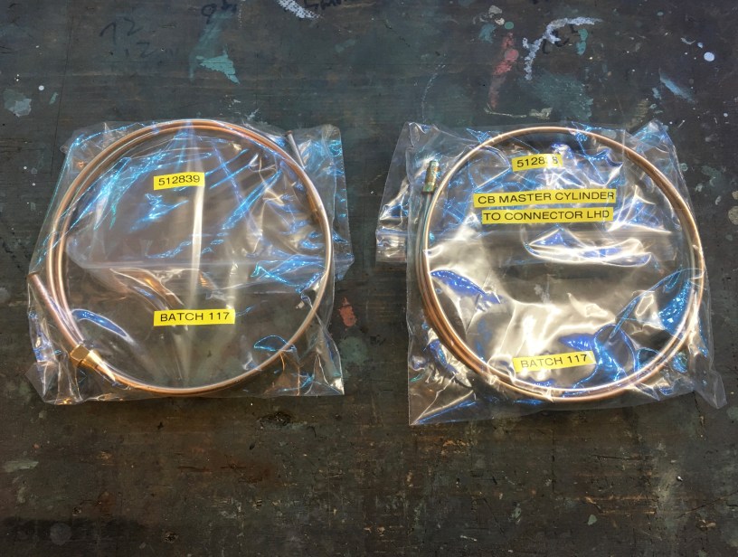
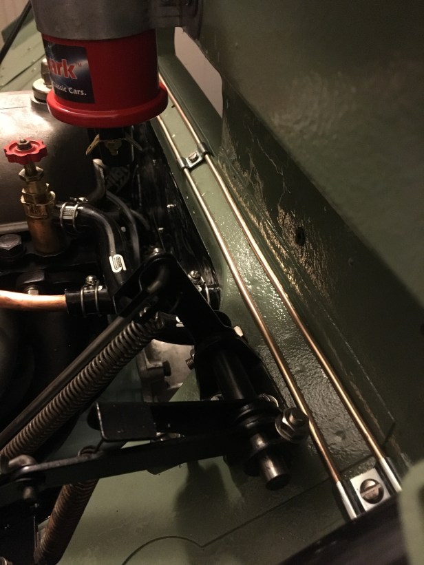
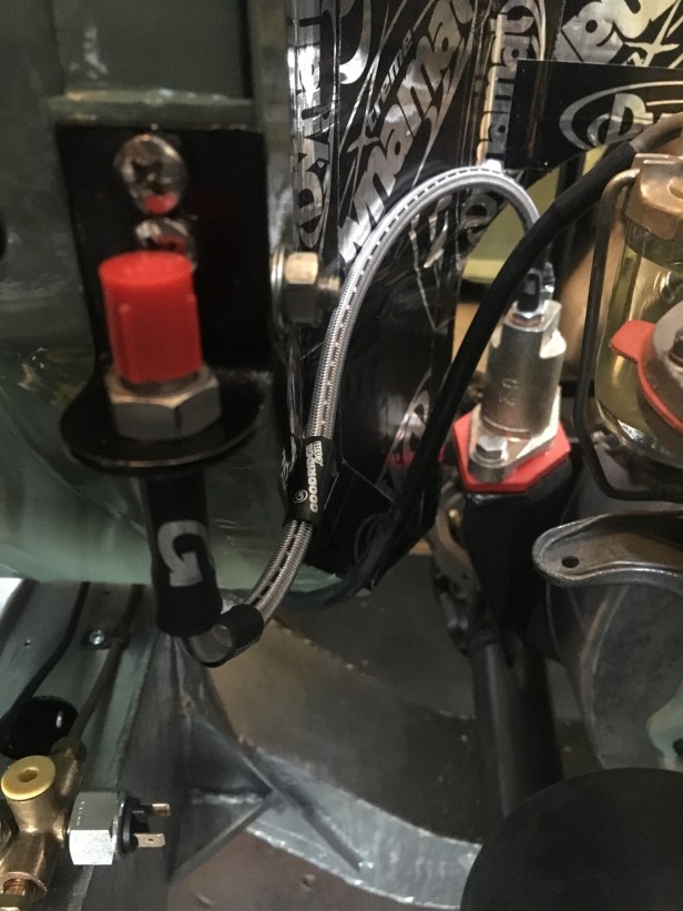
The final job to finish the hydraulic system was to connect the brake and clutch master cylinders to the 5 way block and slave cylinder respectively. The final coils of cupronickel hydraulic pipes from Pegasus Parts were straightened by hand (gently) and the first tight bends made using a home made mandrel…. a length of aluminium tube held in a vice…. after that, the installation was relatively straightforward.


Another great instalment! However, I am curious about the actual routes that the brake lines take. Also I am reluctant to drill holes into the galvanised chassis, for obvious reasons.
Is there a non-invasive way to secure the brake lines to the chassis? I was thinking of placing each copper brake line in a piece of hosepipe and then securing it to the chassis with cable ties.
Do you think this might cause a few raised eyebrows at the MOT station?
LikeLike
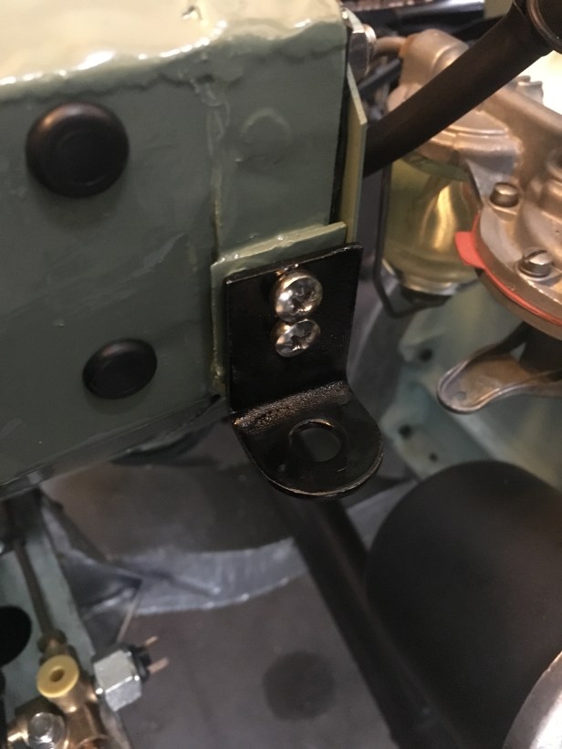
Hi Nick, thanks for the message. I think you’ll be fine drilling into the chassis. Zink has a tremendously strong mechanical bond to the substrate. Unless you’re launching lifeboats into the sea twice a day, I doubt the steel beneath the Zink will blow the Zink off.
I’ve got 3 years worth of Swiss winter salt under my belt and the small penetrations through the chassis have not caused any issues.
Using a mechanical fixing (clip drillled through the chassis) to secure the pipe is probably favorable than running the copper pipe through a hose and securing it with zip ties. If, for example you end up with a tiny pin prick hole
In the copper pipe (extremely unlikely) the brake fluid would track down the hose and you’d never find the source of the leak. I think the MOT station would want to see the pipe for the same reason they rather than having it in a hose.
I imagine there’s thousands of land rovers out there on new galvanized chassis with the break and clutch lines fixed using a clip and self tapper. You’ll be fine!
I hope this helps and best of luck with your rebuild.
Kind regards
Andy.
LikeLike
Thank you so very much for your informative reply. And, No, I will not be taking it into the sea….! Having noted the state of the old chassis when we removed it I am rather in the mindset of fewer drilling’s, the better. But I will probably end up with drilling.
I purchased some brake lines which were specifically cut into sections which are all marked with a letter which corresponds to where they go. They also have all fittings attached. I bought them from Classic Parts Store in Borehamwood.
Regarding the position of the lines, I would be grateful if you could confirm that the line from the rear to the four way splitter should be positioned on top of the chassis. I am guessing it does.
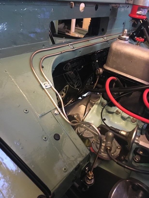
Also the line which runs to the o/S/f connection from the 4way splitter should be laid on the top of the chassis?
Finally, the line from the 4w/S to the n/S front connection I reckon should be positioned on the rear face of the chassis cross member which runs under the clutch cylinder (in order to keep it out of the direct blast from weather and stones) and then on to the top of the chassis and onward to the front n/S connection.
Sorry to be a nuisance but I would like to get it right first time and your pics and descriptions are a great help to me.
Best Regards, Nick
LikeLike
How did this slip through? Sorry Nick.
Yes the line rear of the 4 way splitter sits on top of the chassis until it heads off towards the stop (where the flexible hose for the rear axle connects).
The OSF (I assume you have a right hand drive vehicle) should also run along the top of the chassis leg.
Yes, you pinpoint exactly where the NSF line should run. Behind the cross member for protection.
… and again, sorry for missing your response.
Kind Regards
Andy.
LikeLike