

The final chapter…
When I had Gracie (Series 3 109) in the UK, I had the steering box replaced by the local Land Rover specialist in the next village. I asked for him to keep the old steering box so I had a “spare”. But when I went to collect the vehicle, after the work was done, he said it was such a hassle to get out he just cut it to pieces whilst it was still mounted in the vehicle allowing it to be removed in bite sized chunks.
Having now changed my own steering box, I’m inclined to see the garage owners point of view. At least I wasn’t trying to turn a profit on doing the work.
The workshop manual covers the removal and re-fitment very well if you have a RHD vehicle. On the LHD model, some things simply don’t work.
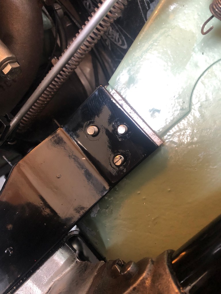
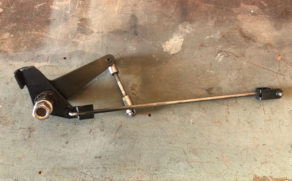
For example, the drop arm puller won’t fit on the drop arm when instructed. It fouls the exhaust manifold. The ball joint on the end of the drop arm, can’t be removed when instructed as this fouls the inner wing and collectively, the steering box, stiffener and chassis mount is almost impossible remove with the mud shield in place.
With my skinned knuckles healing well, it was back into the garage on a drab Sunday morning to install the new steering box!


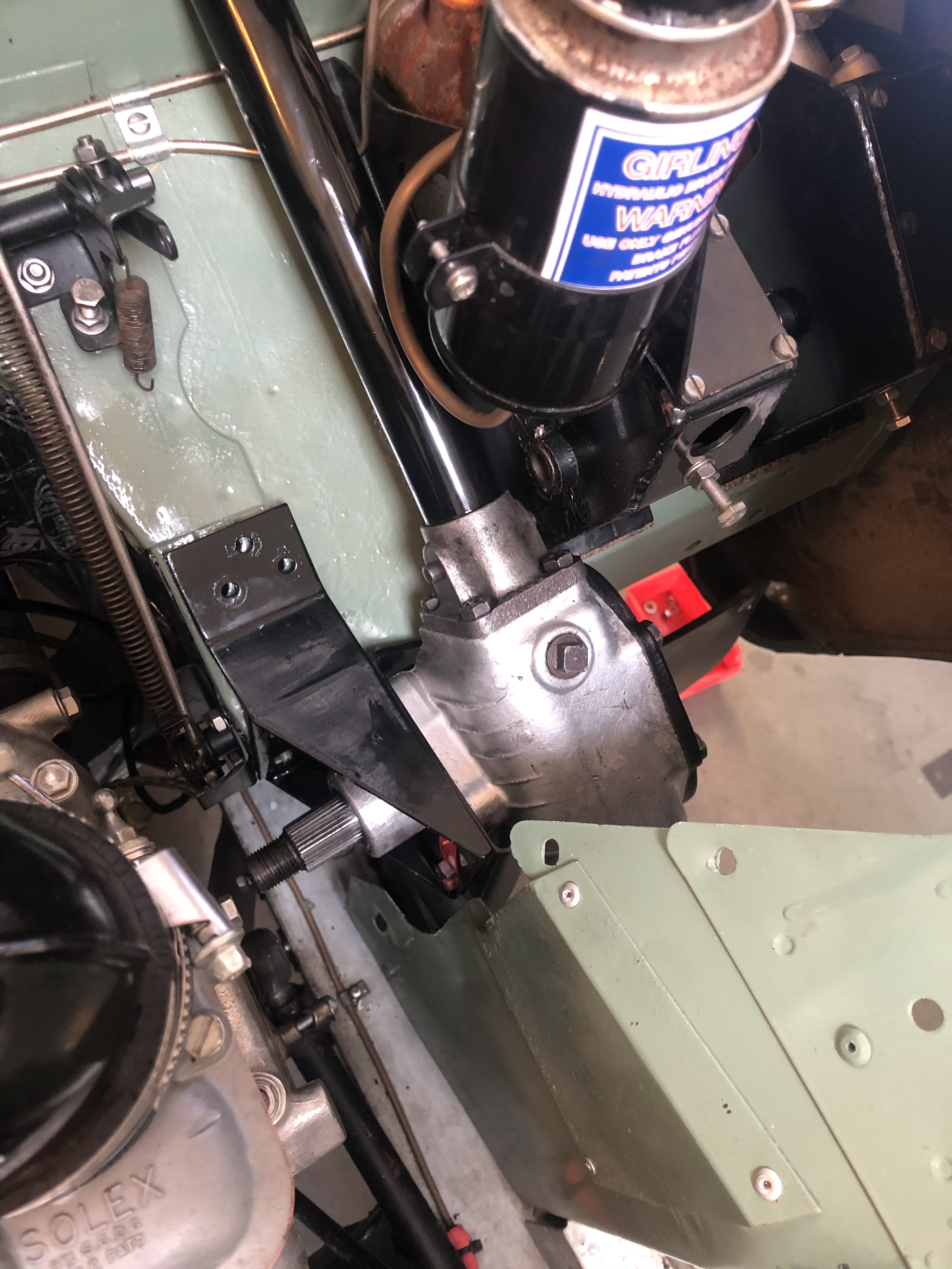
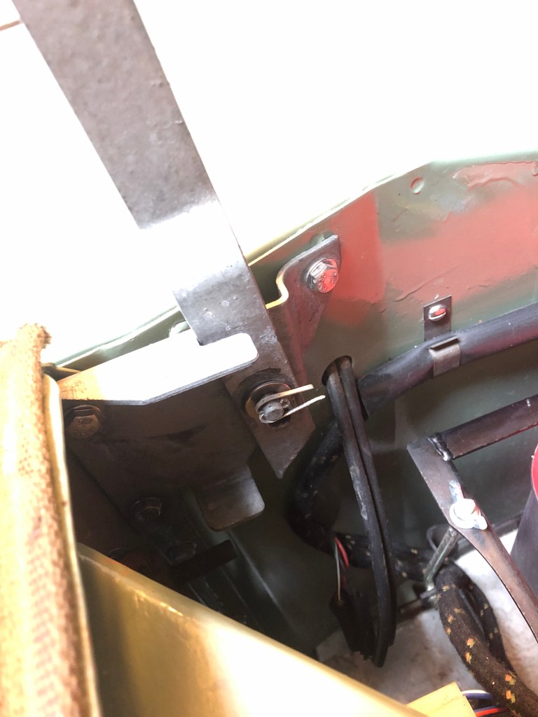
All fixings from this point forwards are only tightened finger tight until the steering column bracket (in the cab) is fitted. This aligns the whole unit. If the fixings under the bonnet were tightened now, the steering column wouldn’t be where it needed to be.

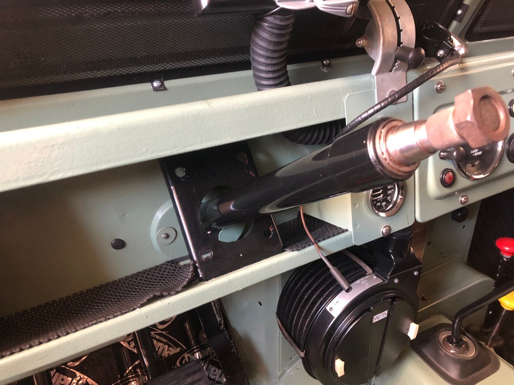

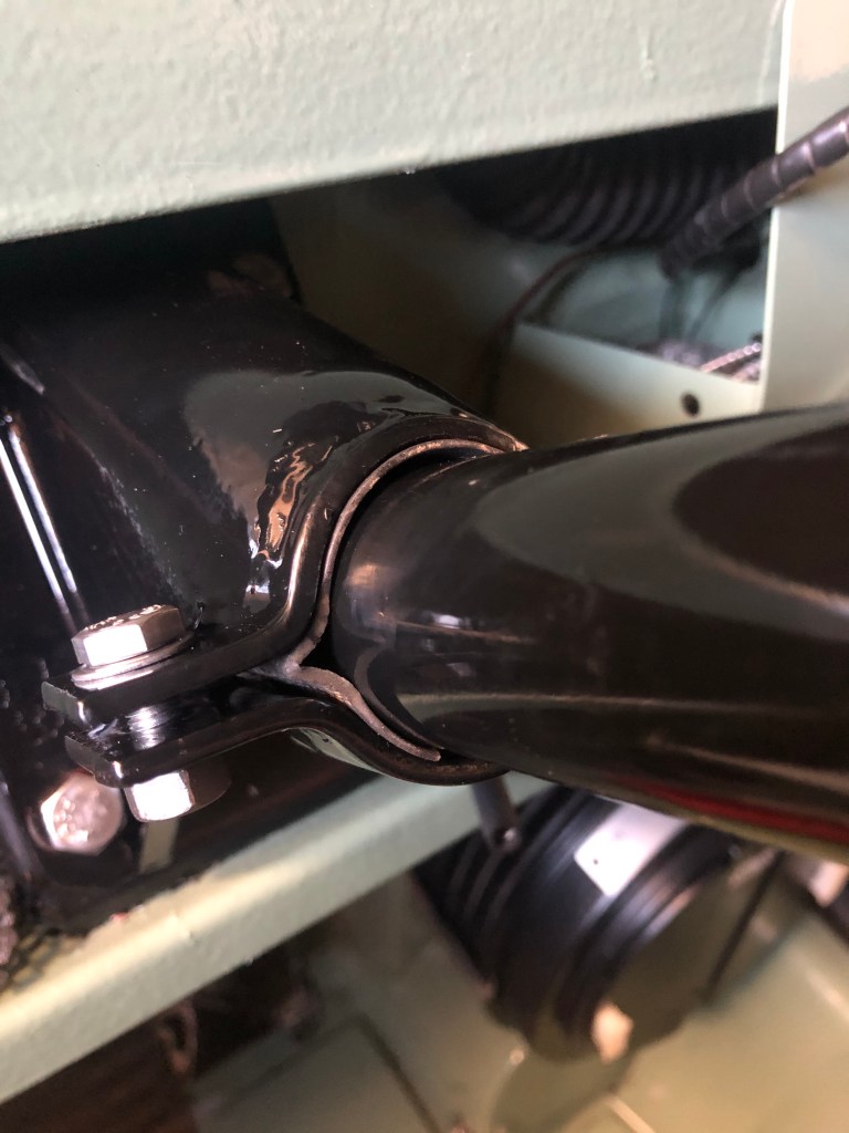
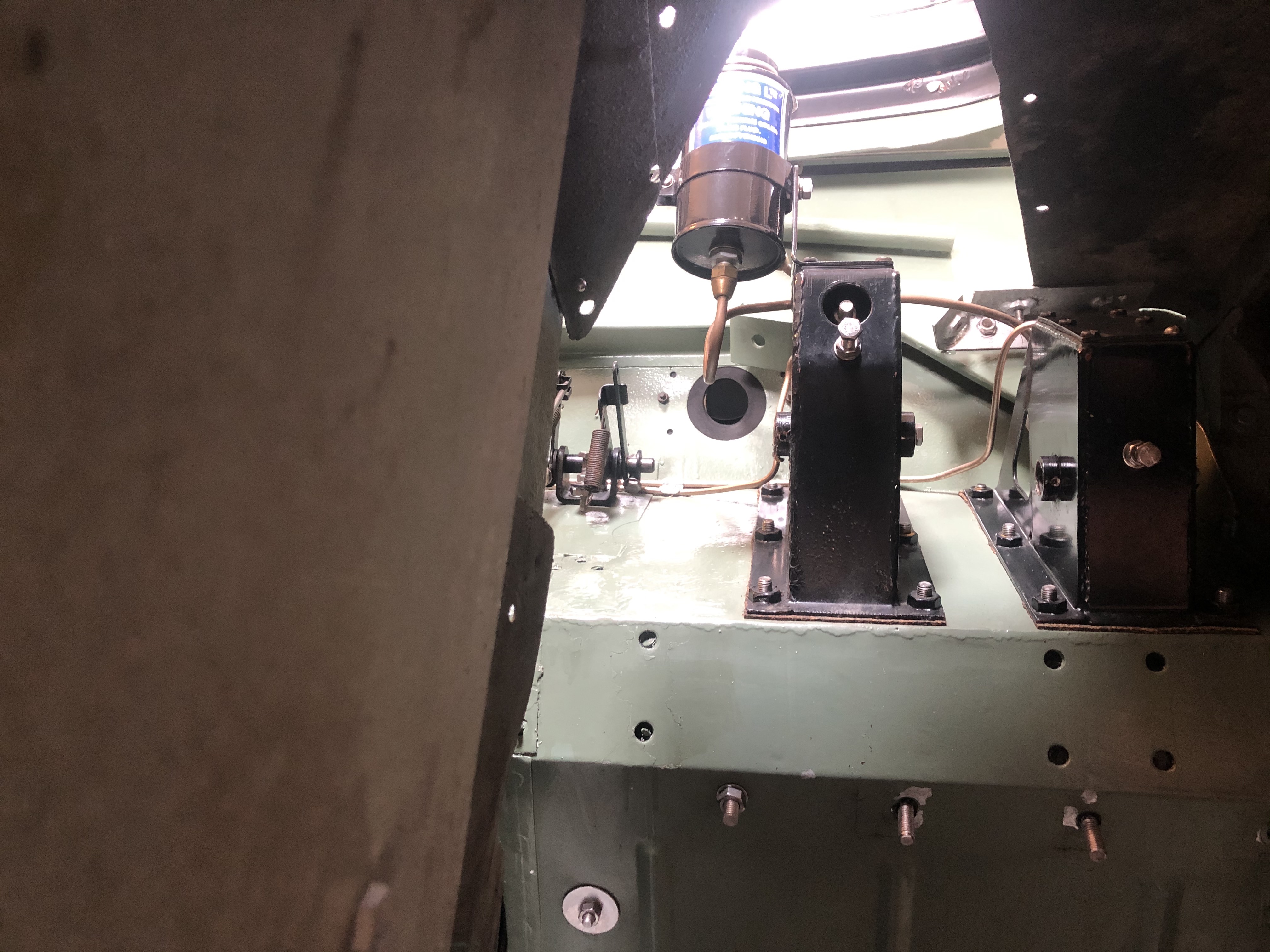
With the steering column bracket installed, it was time to dive back into the engine bay to tighten everything up…


Some time later…


One of the final jobs was to align the driving wheels and refit the steering wheel. The manual says to point the driving wheels in the straight head position. I jacked up the other wheel (the other already having been removed) and turned it to face straight ahead. Given the very slight toe-in, it’s very hard to say when the driving wheels are actually pointing dead ahead but I gave it a try.
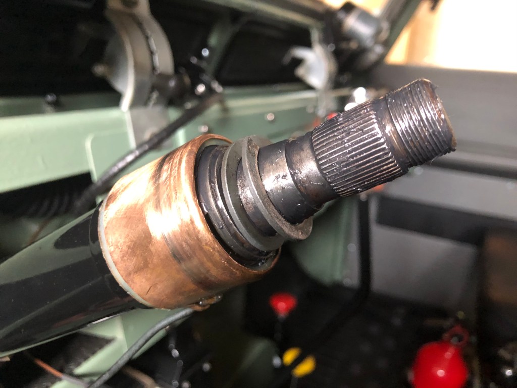
With the wind shot in the dark complete, I then fitted the steering wheel in the “intermediate” (straight on) position.


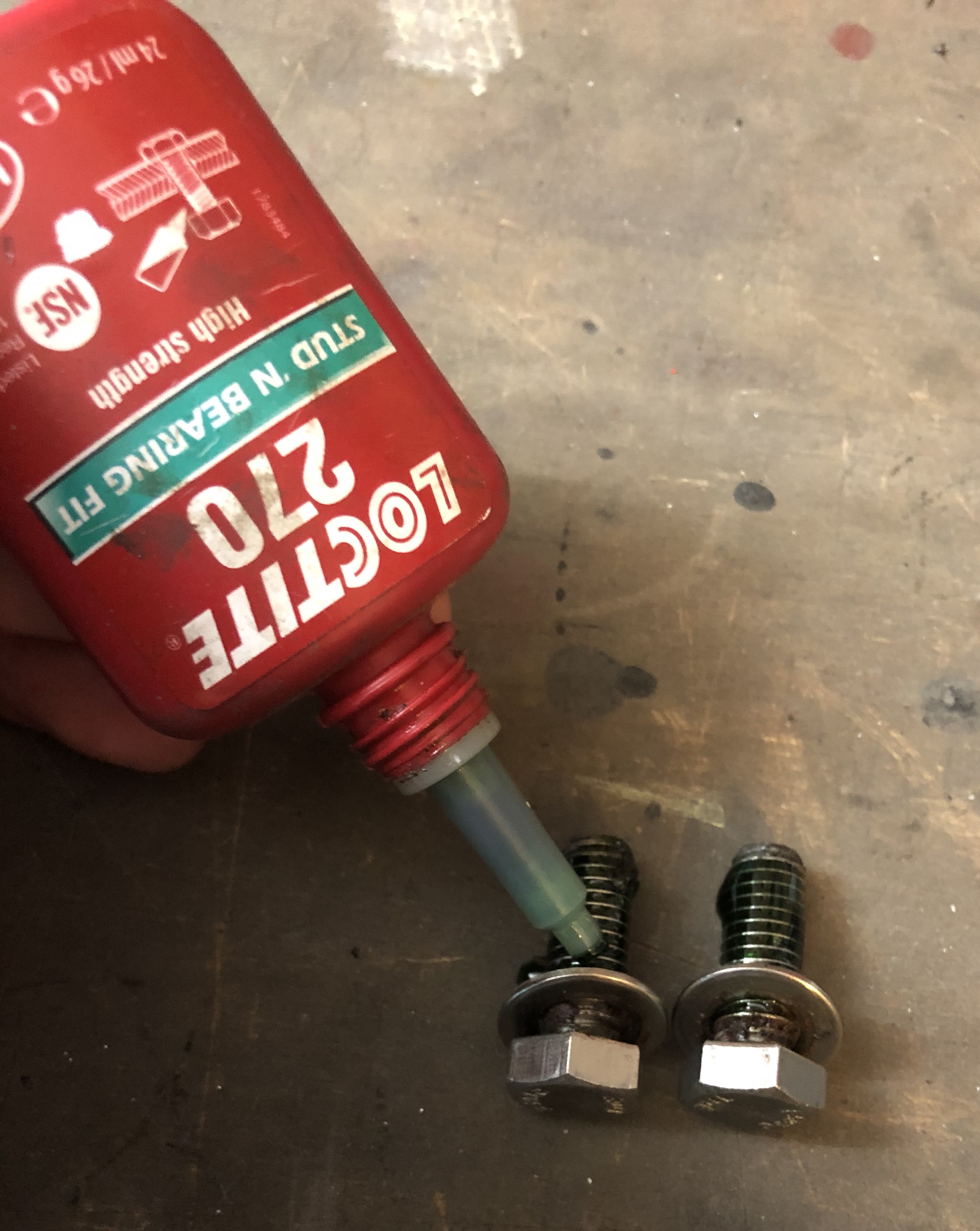
Before I finally shut the bonnet, all nuts and bolts in the steering linkage were checked to ensure I hadn’t overlooked anything. It’s good practice to do this on the whole steering assembly from time to time but especially if parts have been removed and refitted.
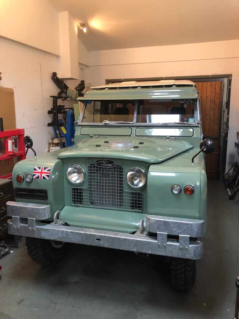
Happy everything was located where it should be, I went for a quick test drive.

WOW! What a tremendous difference in driving the new steering box has made. No more wandering around and much more positive feedback through the steering. Everything felt tight and secure, not like a Series Land Rover at all. It honestly steers like a new vehicle.
My guess at what constituted “straight ahead” when aligning the driving wheels in the garage was absolutely rubbish.
The steering wheel was a 1/4 turn out! Whilst this doesn’t effect the driving experience at all, it looks utterly wrong. It’s a quick job to fix and one for another day.
