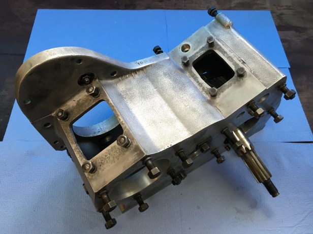
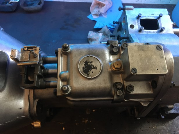
With the engine, clutch, manifold and exhaust system installed its time to carry on with the gearbox rebuild…. and we recommence with the transfer box.
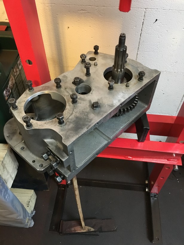
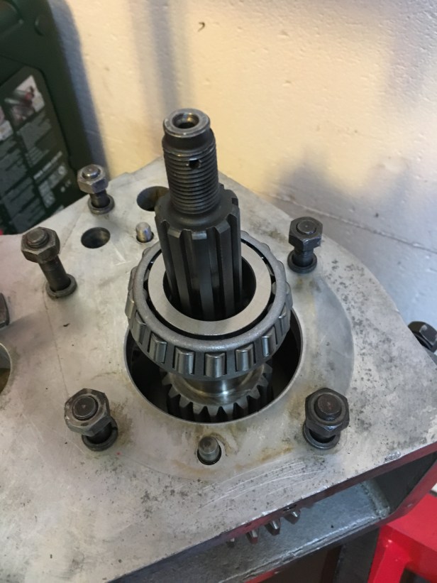
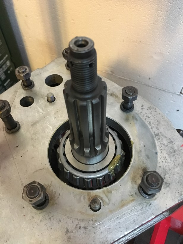
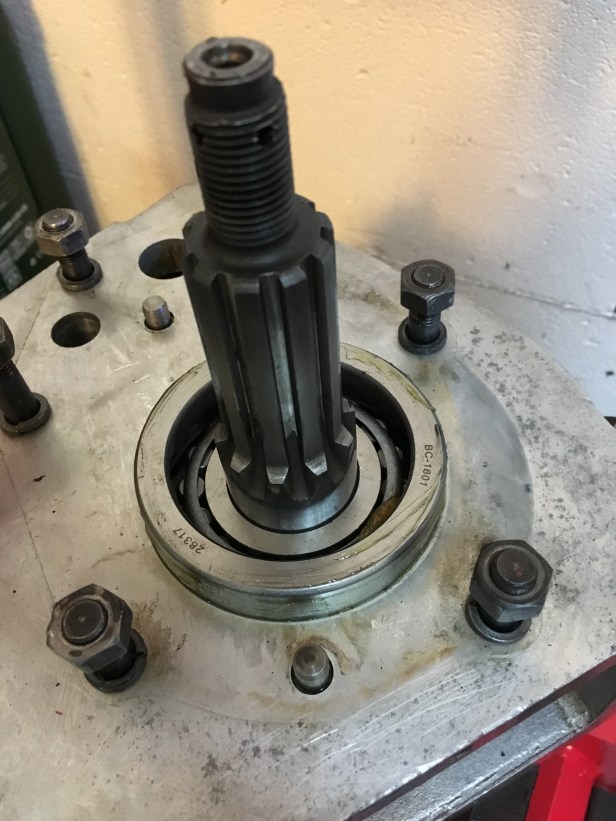
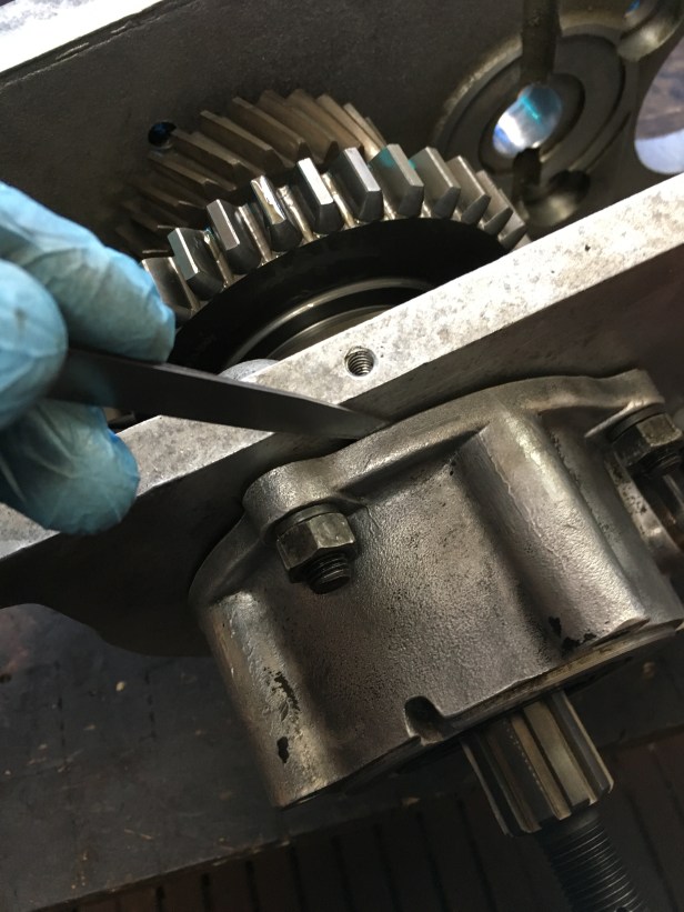
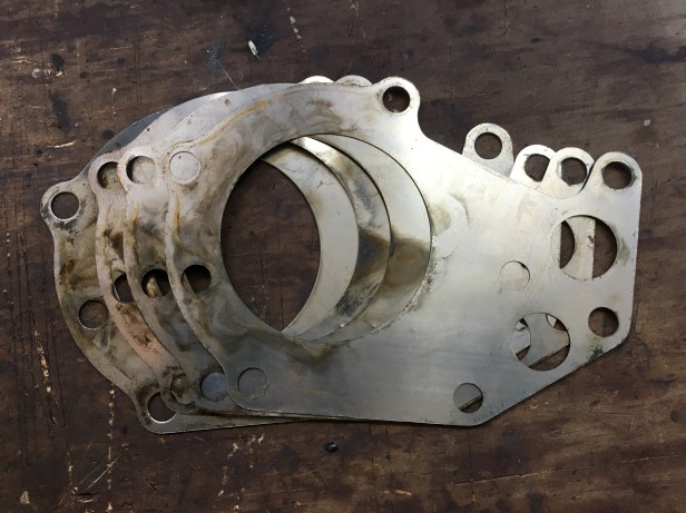
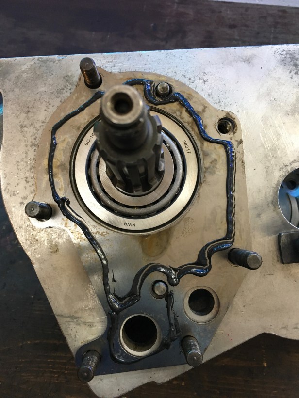
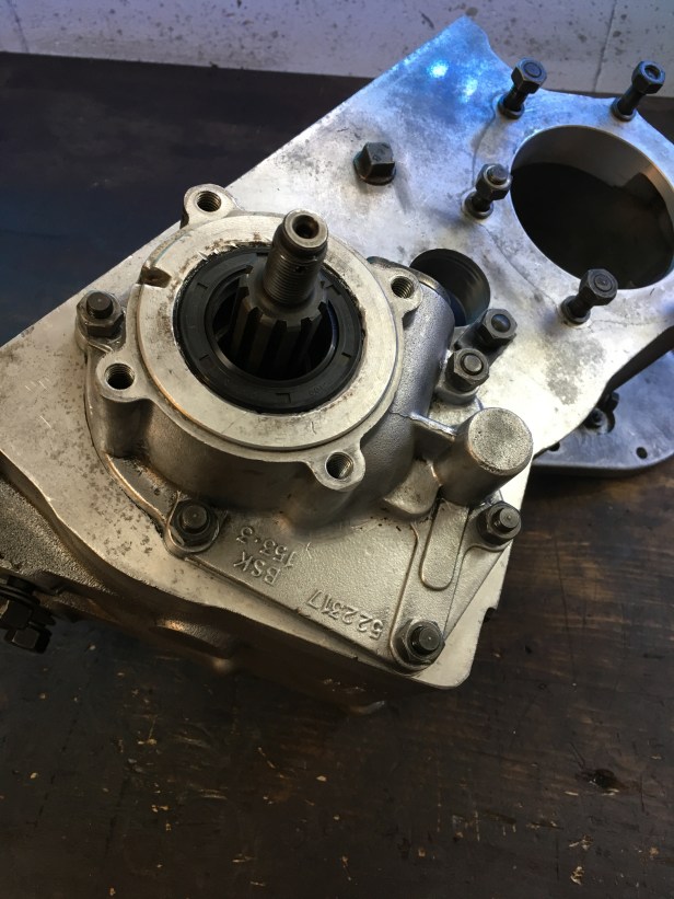
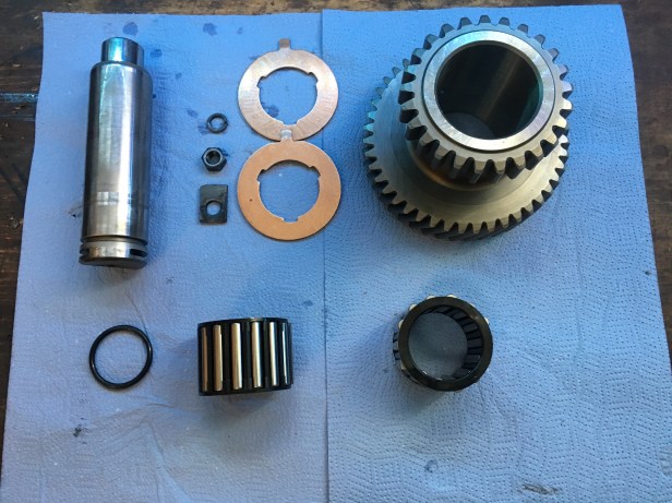
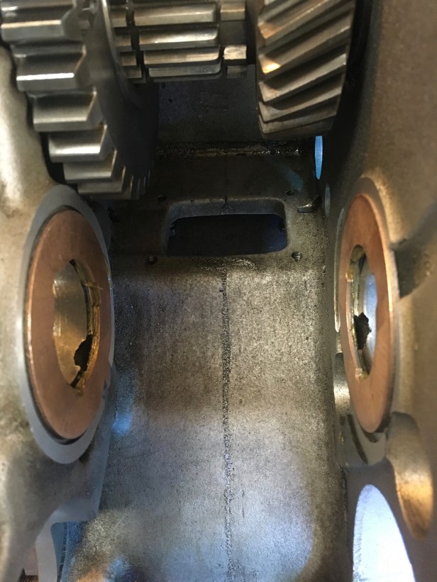
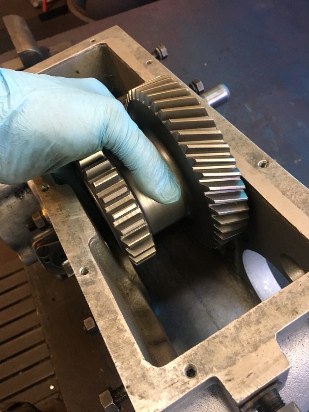
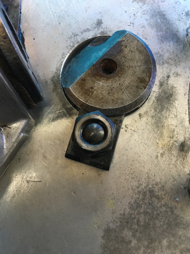
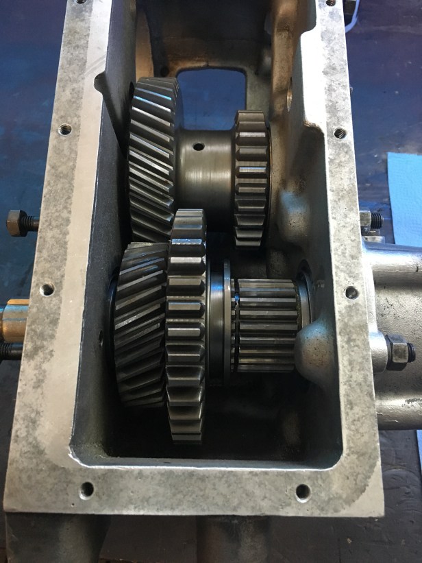
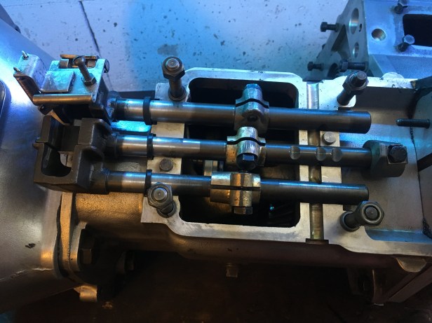
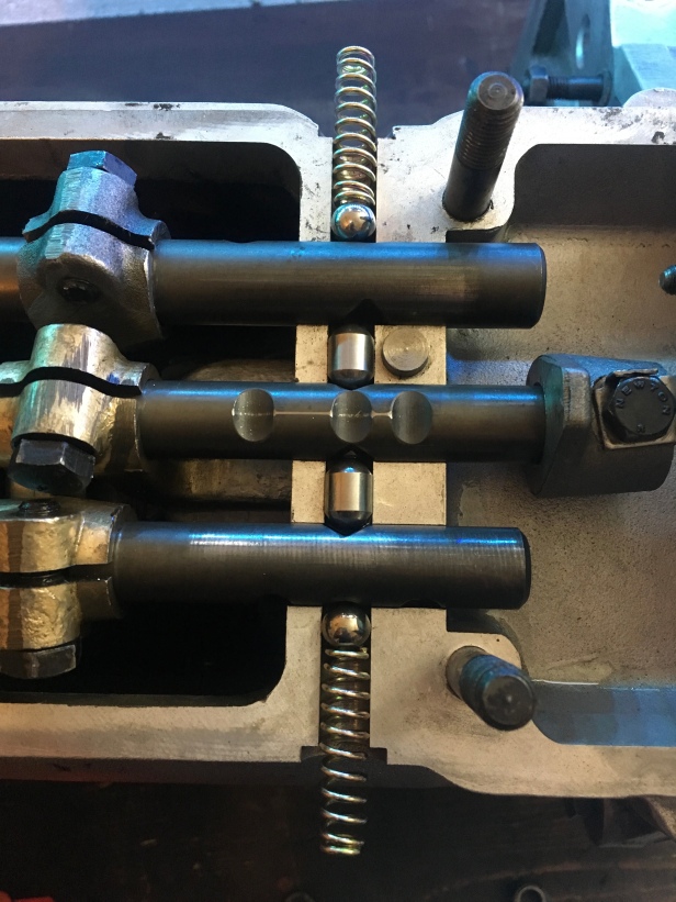
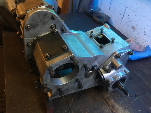
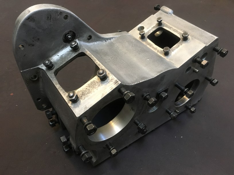
The front output shaft bearing is installed and the shaft is now ready for the rear output bearing….All lined up (with assistance from an offset of plywood), the rearward facing shaft is ready for the new bearingBearing sat loosely on the shaft…Using the the old distance piece from the layshaft rebuild , the bearing is pushed home onto the shaftNext, the bearing shell is pressed into the housing…. but not all the way as the preload has to be set.A slight shoulder is left protruding on the bearing race in order to set the preloadPreload of the bearing is set by first fitting the speedo housing. This housing pushes against the bearing shell…. the more the nuts are tightened, the more force is exerted on the bearing shell, thus increasing the preload. To measure the preload, a spring balance and length of string are used. Once inertia is overcome, the preload should read 2 – 4 LbsOnce preload is set correctly, the gap between the gearbox case and speed housing is measured using a set of feeler gauges…..…. and the corresponding thickness of shims insertedFor belt and braces, some gasket sealant is used between each shim with the aim to eliminate oil the typical leaksShims, worm gears and speedo housing installed. On rechecking the preload it read 5 Lbs. Close enoughIntermediate gear assemblyThrust washers installed with the aid of a little grease on the rear faceNeedle bearings installed into the new constant gearIntermediate gear offered up to the case….…. and shaft pushed homeLocating tab in placeWith everything installed, the end float of the intermediate gear can be set. This is the gap between a face of the gear wheel and the thrust washers. All checks out OK, within tolerance (0.010mm). The intermediate gear is then removed to allow the fitting of the main box and refitted laterWith the main and transfer box reunited, the next step is the selector shafts. New seals are fitted to the shafts.New dedent springs are fitted to the shaft. The purpose of the these springs and balls is to locate in the indentation on the shafts as the gear is changed.Top cap in positionTransfer case largely back together. There is a new billet old cover from Roamer Drive and at some point in the near future an overdrive. The latter will locate in the remaining round opening on the back of transfer case.