DYNAMO: from the Greek dunamis,“power”… (bet you didnt know that. Don’t worry, I had to look it up)
“A machine for converting mechanical energy into electrical energy, typically by means of rotating coils of copper wire in a magnetic field”
A common modification on older Land Rovers is to replace the Dynamo with an Alternator, If you run a lot of high current ancillaries (spot lights, winches, fancy stereo system) the alternator conversion is for you.
As LGL won’t have any of these additions, we’ll be sticking with the original Lucas C40. Even better, all the lights will be LEDs, so there isn’t even the high current draw of halogen bulbs.
There’s a myriad of reasons an alternator is more favourable over a dynamo, most of them largely make sense….. but…… the old Lucas C40 just looks right and has been taking care of the the electric needs of LGL for 50 years, so with a strip and inspection, it will hopefully be doing the job for another few years.
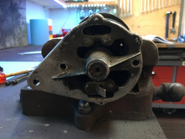
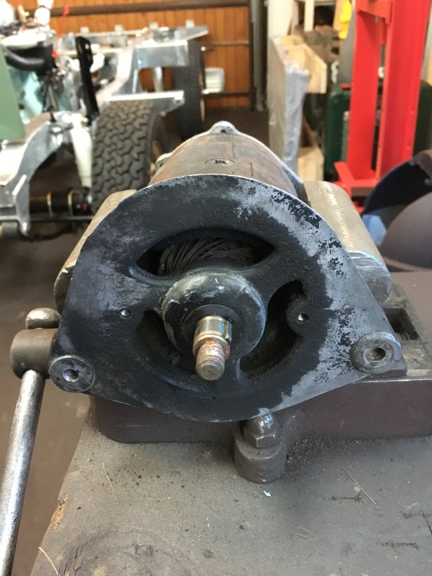
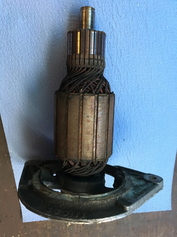
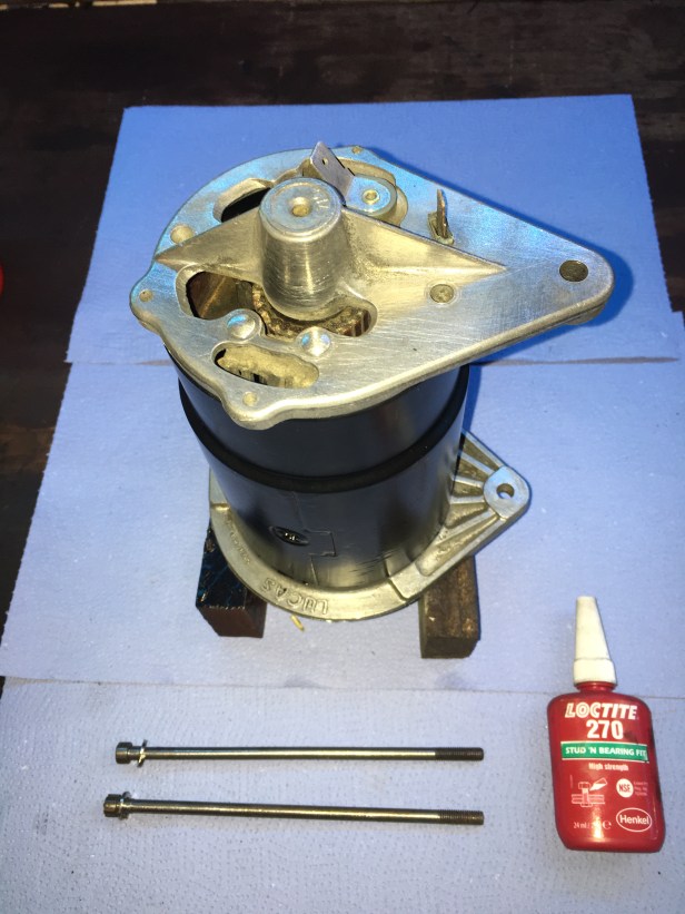
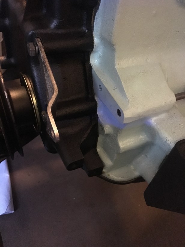
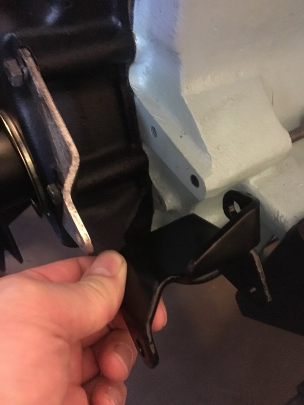
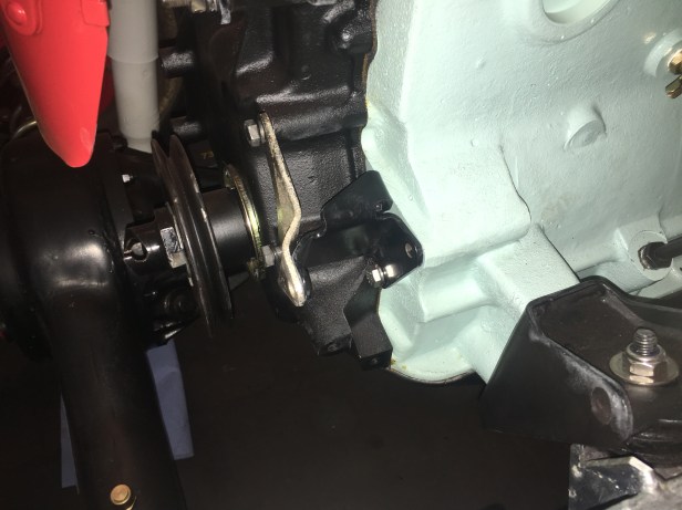
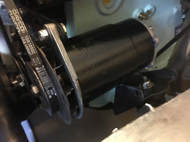
Starting pointSet in the vice a puller is used to remove the belt pulleyThe terminal end. The +ive and -ive cables take the current feed to the regulator on the bulkhead and on towards the battery.The pulley end. Note the woodruff key in the shaft… which was s stubborn little thing and refused to shift.Aside the bearing in the (other) end cap, the only serviceable items are the carbon brushes. They can be seen (just about) located in their copper holders. The brushes press against commutator on the end of the armature and transmit the electrical energy into the wiring loom. These brushes look to have been replaced fairly recently, there’s plenty of life left in them. I couldn’t get the woodruff key out of the shaft, so the clean up had to be done with the end plate still attached to the armature. (Commutator is the narrow end of the armature)Case and sundry brackets ready for primer and top coatEverything cleaned up, painted and ready for reassemblyArmature and end plate back togetherYou can see how close the armature runs to the magnetsBoth ends on, shaft bush and bearing oiled and ready for the two long set screws to be installed. A dab of thread lock for luckDynamo and fixings finished and ready to installed on the engineSuccessful test of the dynamo by spinning it up with the power drill. (The multimeter is reading in mV)The Dynamo fits in this gap and takes a belt feed from the crank pulleyThis complicated little bracket fits in hereBracket in place. The rest is straight forwards. One long stud at the rear passes through the engine block and supports the rear of the dynamo. The front end is supported by a bolt through the silver bracket. Some packing washers are used to ensure the centre of the pulley lines up with that of the crankshaft pulleyDynamo loosely fitterNew fan belt installed, with the correct tension set and remaining fixings tightened up


Thanks very helpful and nice clear pictures
LikeLike