
Before I delve into this topic I’d just say that if you are in anyway uncertain about the operation and maintenance of your brake system (on any vehicle) take it to a professional. The following is by no means an in-depth guide on Series Land Rover brake system overhaul / maintenance and should not be take as such. My working knowledge of this topic comes from the one source of information you should be using…. Land Rover Series II & IIa Repair and Operations Manual. Part number AKM8159
Now that’s out of the way, lets begin…
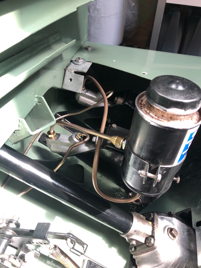
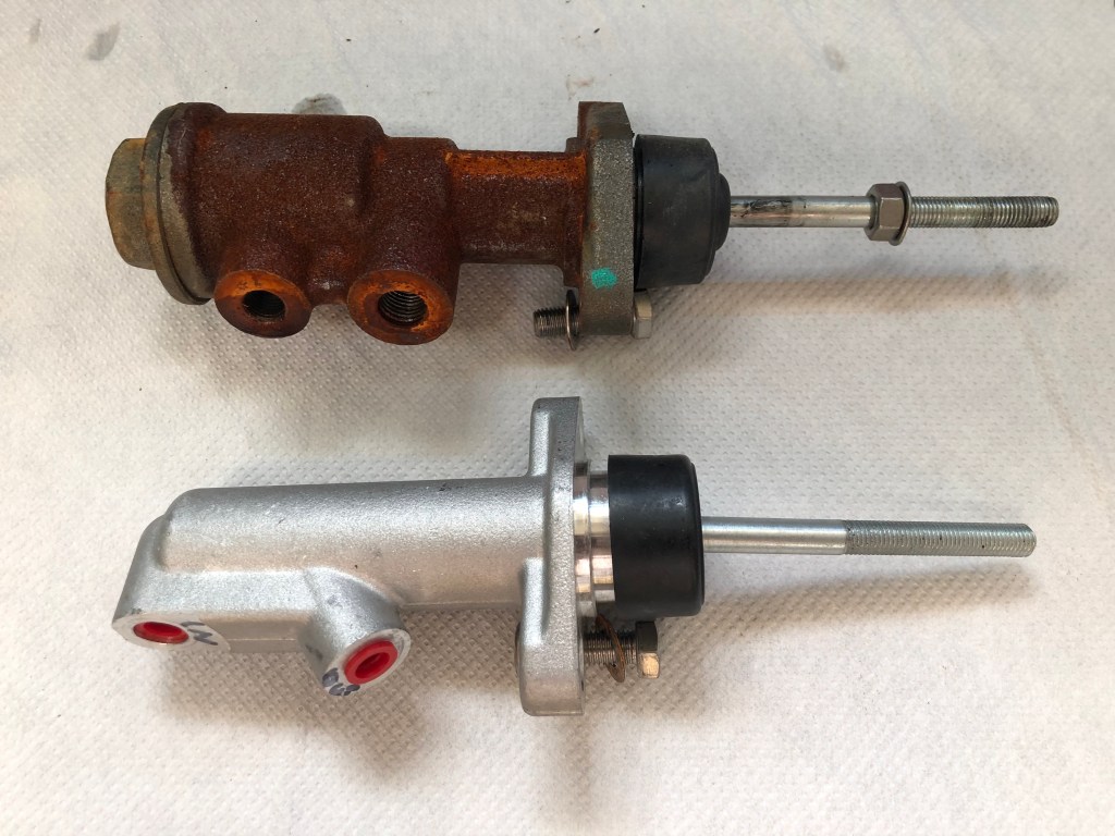
There are two types of brake master cylinder for the Series Land Rover. The Centre Valve (CV) type and (Compression Barrel) CB type. The workshop manual states that the CV model is “normally” fitted to 88” models and CB to the 109”.
During the rebuild, I had decided to fit the CB type. I (wrongly) assumed given its larger physical dimensions that it would offer additional braking. It doesn’t.
In the 3000km LGL has been road legal, I’ve alway thought the brakes could be better. There’s only so far you can go with a non servo drum brake system but the set up I had, certainly had room for improvement.
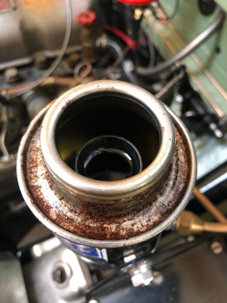
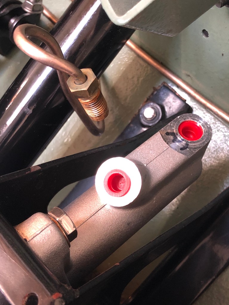
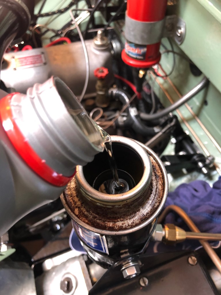
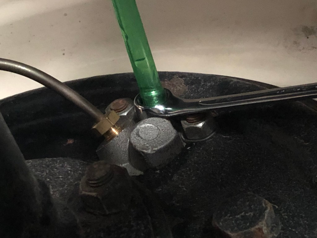
The CB brake master cylinder had the tendency to trap air under the seal at the cap end. This air gap should be filled with brake fluid. The workshop covers this topic and advises that the correct Castrol-Girling pressuring filling equipment be used.
I obviously don’t have such a thing but the local classic car garage did and they bled the system for me. Even then, it still felt spongy. Despite this I could stop when required and as I don’t hoon around the country side as if I’m in a Subaru, it was never a problem.
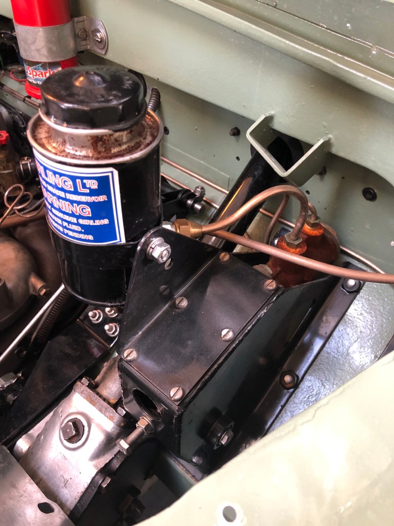
The CV master cylinder is identical to that used for the clutch and when I installed that, it bled first time and I haven’t had to touch it since.
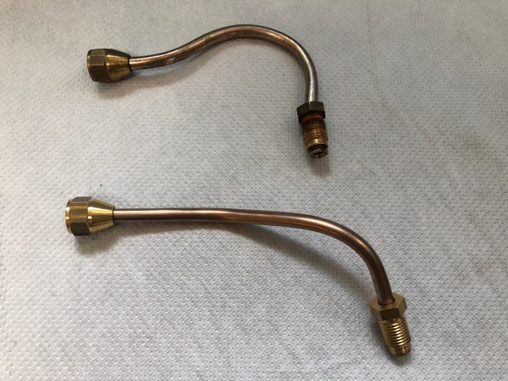
Somewhere along the line, I’d ordered a new CV brake master cylinder and as I’d already drained the brake fluid out of the system to fit the rear differential guard, it made sense to swap the brake master cylinder over.
Removing the CB brake master cylinder
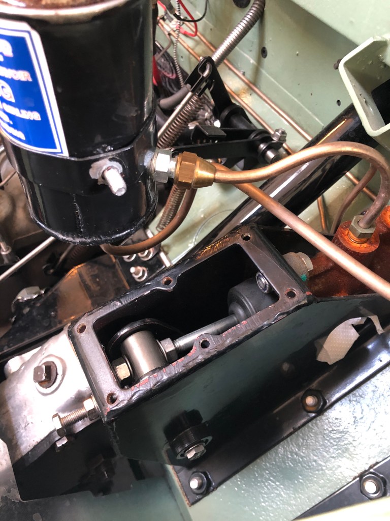
BUT… as I move the correct page of the workshop manual… to remove the CB master cylinder, the brake tower needs o be removed from the vehicle as the cylinder is too long to clear the bulkhead. This was very quick to do and took only a few minutes… sorry no photos.

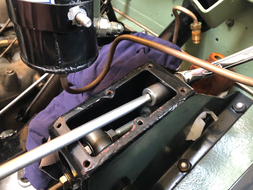
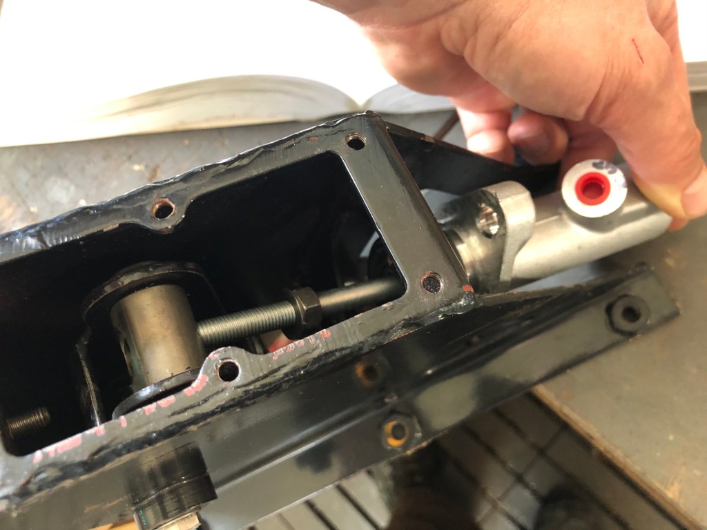
Fitting the CV master cylinder:

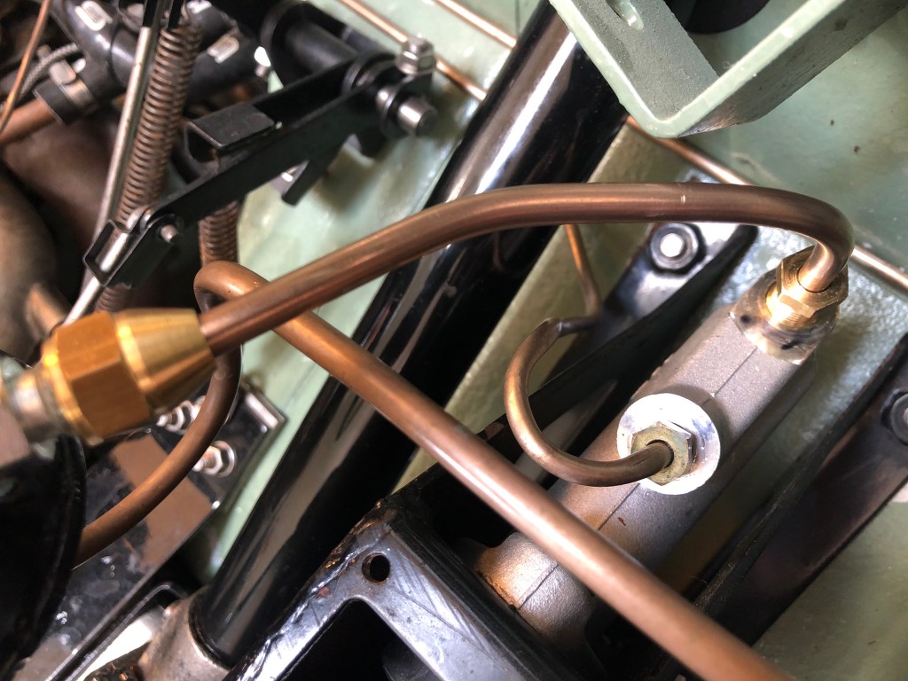
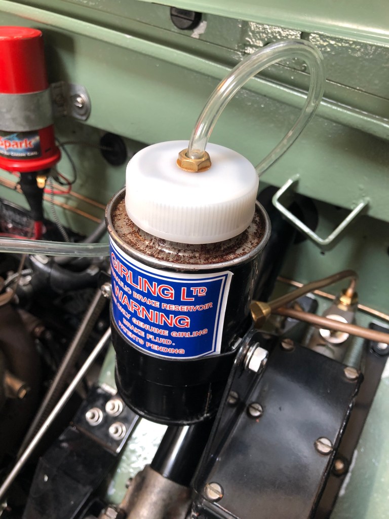
Bleeding the brake system:
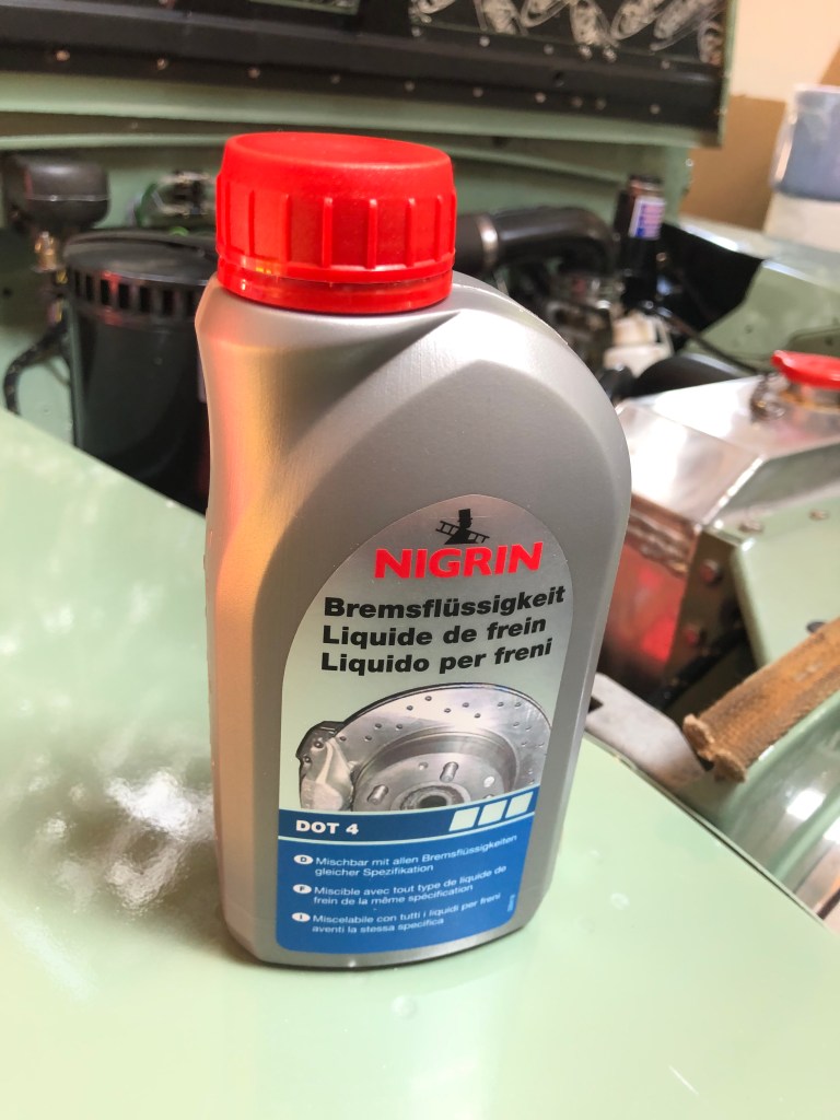
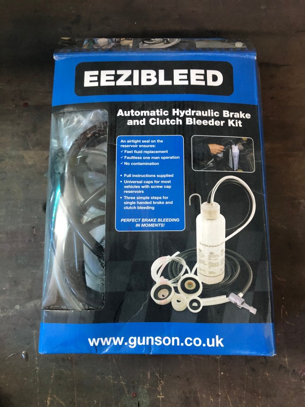
Bleeding brakes manually requires two people. One to pump the brake pedal, one to loosen and tighten the bleed screw on each wheel cylinder. It can be a long process. The Eezibleed makes the operation a single handed one.

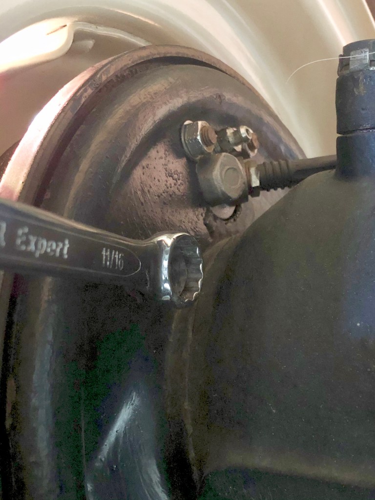
Air is bled from the system at each of the 4 wheel cylinders. These are the components that do the actual braking. When you push the brake pedal, the wheel cylinder expands and forces the brake pads against the inside of the brake drum. The friction thus slows the vehicle down.
To ensure no air gets trapped in the wheel cylinders, the snail cam is backed off to ensure the pistons on the cylinders are pushed right back inside.. i.e. the brake pads are the furthest away from the inside of the drum as possible.
The snail cam is used to adjust the brakes from time to time as the friction material wears down.
I keep the screw open for 5 seconds after the fluid arrives and no longer contains air bubbles. The excess fluid runs into the jar. Periodically, this is used to refill the reservoir.
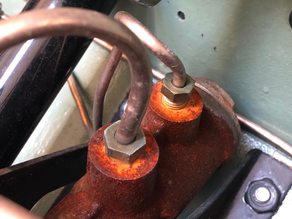
To bleed the system correctly the manual states you must start at the wheel cylinder furthest away from the master cylinder and work you way around the vehicle to the wheel cylinder closest to the master. The distance refers the length of pipe runs, not the physical distance. For LGL it’s; drivers side rear, passenger side rear, drives side front, passenger side front.
To ensure all the air was out of the system, I cycled around all wheel cylinders 4 times.
Once that was done and I was confident there was no more air in the system, the brake pads were adjusted using the snail cams. This is why I had all 4 corners up on axle stands. It’s important you can spin the wheel to feel when the brake pad touches the brake drum. When you hear the pads touch, back the cam off so the wheel spins freely.
Job done and the brakes feel a lot firmer than before.

Hello
Very nice post.
Do you confim that it is a LHD model ?
The tank is mounted on the brake cover plate and not on the clutch cover plate ?
Thank you for your answer.
Gilles.
LikeLike
Hi Gilles, thanks for the message. Yes, the vehicle is LHD and the combined brake and clutch reservoir fixes to the brake tower. It is not possible to fit it to the clutch tower as the wing top and edge of the bonnet are in the way. Hope this helps. Kind regards. Andy.
LikeLike
Hi Andy
Sorry for my late answer and thank you for your quick reply.
I have also a LHD serie 2A 88 (softop 1969).
Unfortunately my clutch reservoir is fixed on the clutch plate (under the wing).
Base on your feedback I know that it is of course wrong and I have to fix it because I can’t control the level of oil 😦
In addtion I have leaks in the clutch master cylinder and also at the reservoir level.
I bought a new Girling reservoir and a new TRW CV clutch master cylinder exactly the same like yours.
The issue I have is to give the correct specifications to my mechanic to make the correct pipes because it is not specified in the documentation (reservoir and master cylinder)…and I’m not sure that the existing unions and flare are correct…
Based on different sources, my understanding is the following:
1) Reservoir to master cylinder IN (brake and clutch):
– 3/16″ Kunifer Brake Pipe (I sew sometimes 1/4″ )
– From reservoir : Female Brass 7/16″ 20 Tpi Brake Pipe Unions UNF – SAE Double inverted flare
– To master cylinder: Male Brass 7/16″ 20 Tpi Brake Pipe Unions UNF – SAE Double inverted flare
2) Master cylinder OUT
– 3/16″ Kunifer Brake pipe
– Male Brass 3/8″ 24 Tpi Brake Pipe Unions UNF – SAE buble fare ?
Do you recommand Brass or Steel ?
Thank your in advance for your help.
Gilles.
LikeLike
Hi Gilles, sorry for taking so long to reply. It’s been a busy time. I would suggest you buy a compete set of pre made clutch lines from Pegasus Parts. All ends are made off, with the correct sized unions.
https://www.pegasusparts.co.uk/ourshop_90073/cat_1656591-333-Clutch-and-Brake-Pedals-and-Master-Cylinders.html
They also stock the correct, mandrel bent reservoir to master cylinder pipes.
To be honest, I’m no expert on the individual union and pipe sizes… especially in inches. I grew up with millimeters 😊
Hope this helps and apologies again for the long delay.
Kind regards
Andy.
LikeLike
Hello Andy
Thank you for your reply.
I’m aware my question was not easy but because I have in my car some mistakes I became suspicious.
The link above and another source confirme the 1/4″ size for the pipe betwwen the reservoir and the cylinder (the other pipe ar 3/16″).
Congratulations again for the quality of your web site which is a valuable source of inspiration.
Gilles.
LikeLike
Hi Andy, may I pick your brains on a brake issue on a very early RHD Series 3 88″ with a CV type master cylinder? All new decent quality brake parts fitted and system bled. When I pump the pedal a few times it builds up pressure in the system and the brakes are applied. When I back off the pedal halfway, the brakes are released but the system remains pressurised and I can reapply them quickly. However when I fully release the pedal the system loses all pressure and I have to pump the pedal several times to get braking power back. Any thoughts on what might be happening?
LikeLike
Hi Andy. I have similar issues. It takes two presses of the pedal to have a rock hard pedal. This has been my experience in general with Series Lane Rovers. Assuming there is no air in the system the need to pump the pedal arises to expand the wheel cylinders enough for the brake pad to engage with the inside of the drum. You could adjust the snail cam one more notch so the pad is closer to the drum…. If that still doesn’t help, then I’d re-bleed the system. Hope this helps. Cheers. Andy.
LikeLike
Hi Andy, thanks for the reply! With mine it probably takes about 4 or 5 presses to make it work so I think there must still be air in the system. Time for another bleed although I’ll do what you said and I’ve had a couple of other tips. Love your LGL by the way. Mine is extremely ratty by comparison. Maybe we’ll cross paths one day in the Bernese Oberland if you ever head that way. Cheers, Andy
LikeLike
It is very bad practice to reuse brake fluid bled from the wheels and put it back in the reservoir. This will contaminate the whole hydraulic system. Always use fresh brake fluid to top up.
LikeLike
Hello There. I am in the process of replacing the clutch and brake master cylinders on my 1966 IIA. I’m going back with the original style cylinders (CB master for brakes and CV for clutch). I’m confused on how the 1.5mm freeplay on the piston/pushrod is measured? With the pedal spring attached I cannot feel the point as to when the pushrod is coming into contact with the piston? Additionally, the manual mentions reattaching the fluid reservoir and refilling with fluid, prior to taking this measurement. With the fluid reservoir attached, the cover plate has to be on, so how can this be adjusted? I haven’t been able to come across much more detail on this process, so since it seems you have done the exact thing, I would greatly appreciate any assistance you could offer. Thanks, Matthew
LikeLike
hello, I am new to my 1963 series 2a 88.
I am trying to base line minor areas before I go into extensive restoration projects.
Right now I’m replacing all for brake shoes, drums, cylinders and hoses and getting ready to bleed the lines.
I’ve read your post ( great BTW) but I’m confused on which wheel to start. My green book on page 22-H says to start at the wheel nearest the master cylinder but you said start at the fastest. Am I missing something. I think you’re correct but I want to get your opinion.
thank you.
LikeLike
Sorry for not responding sooner. I think I picked the idea up of bleeding the system starting from the furthest wheel cylinder from the Series 2 forum. The idea being that, you expel the maximum amount of air / old fluid before moving closer to the master. It worked for me but I imagine the workshop manuals guidance will also be fine too.
LGL
LikeLike