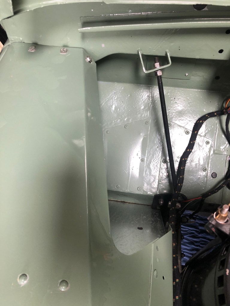
At some point in the past, LGL had the top of the drivers side wing cut open to allow access to the clutch master cylinder.
The workshop manual suggest that if the clutch master cylinder needs to be accessed, the whole wing needs to be removed so it’s not unusual to see the top of the wing cut back.
Later models (with a servo on the brake master) was sculpted to allow the servo to fit and better access to the clutch master.
I wasn’t that fussed about this rather savage enhancement of the wing top as it can only be seen when the bonnet is opened but it did allow rain water to drip down into the foot well.
As any Land Rover owner will know, having water leak into the vehicle is all part of the… charm but cold water dripping into the footwell leads to cold feet and steamier windows.
I had previously expertly repurposed an old chopping board (it was rubbish at being a chopping board) to close the gap. Not surprisingly, this didn’t last that long but it did stop water ingress to the drivers footwell.
A similar more permanent, removable solution was needed. On on…
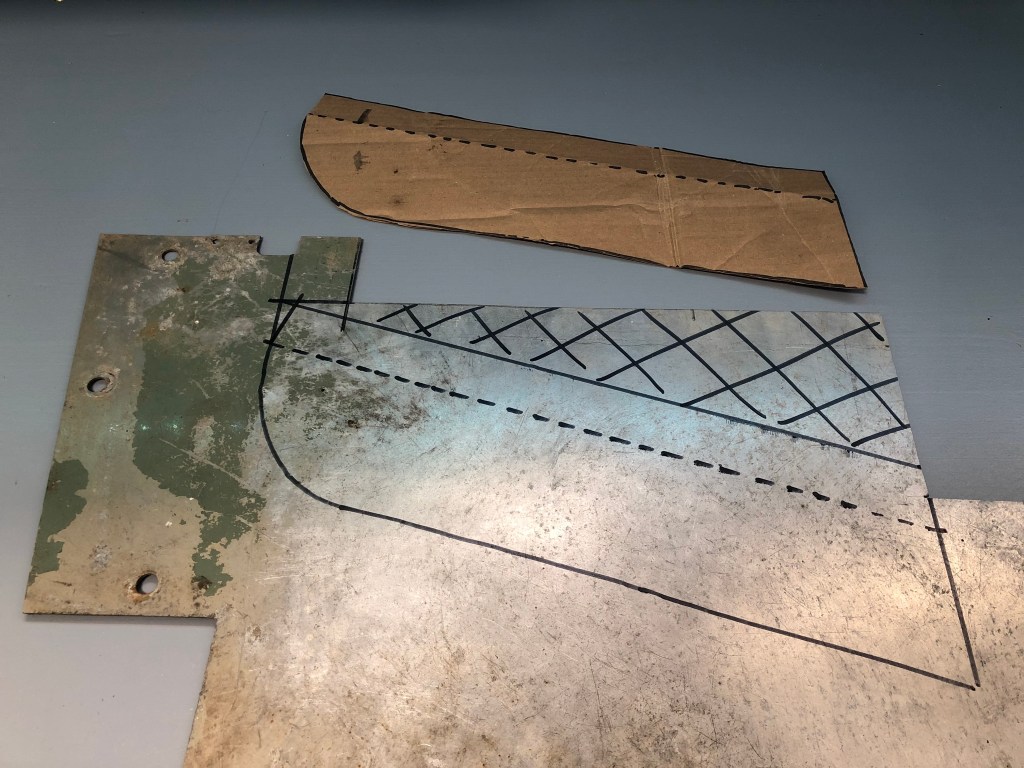
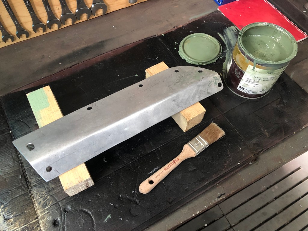
This is the rather raggedy edge left from someones angle grinderBy comparison, this is the passenger side. Nice lines…A cardboard template was fashionedThis was transferred onto a piece of aluminium. In this case, I’m using the original passenger side floor panel. Technically its not aluminium, it’s Birmabrite; the trade name of the UK firm who made it and contains small %ages of magnesium and manganese and is highly corrosion resistant. Ready to make a noise…With the (rather wobbly at this point) panel cut out, it was time to bend along the line. Some time later and after a moderate about of abuse with the lump hammer a reasonably consistent fold it created. I removed the wobbles in the top edge with the angel grinder and offered it up. Not bad eh?The panel will sit below the wing top. The mud shield had to be loosened so I could fit it underneath. I can now mark the holes.The locations were centre punched and a pilot hole drilledI plan to use a Rivnut insert. An M6 bolt Rivnut requires a 9.5mm hole.With the holes drilled, it was time for a good rub down with some acetone and a quick coat of paint to match the surroundings.
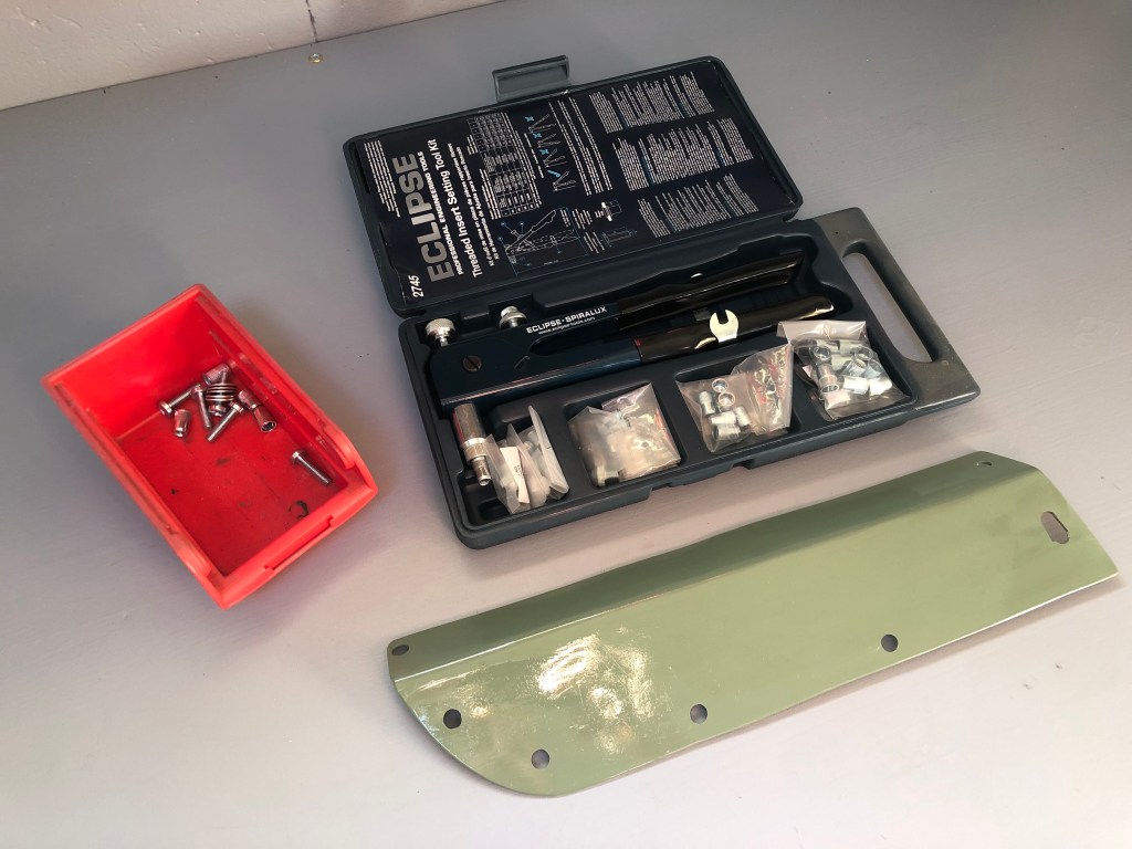
Next morning…
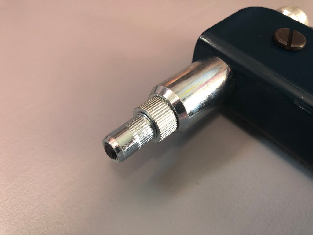
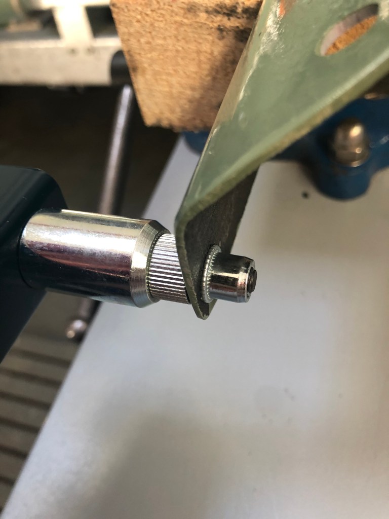
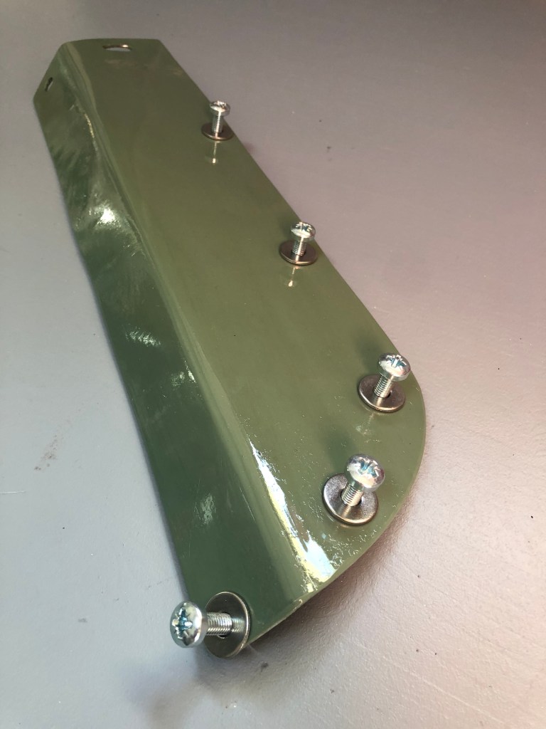
New panel, fixings and Rivnut kitThe M6 insert is loaded onto the mandrel. I’m using stainless steel inserts. I’ve found with the aluminium ones it’s very easy to rip the threads out whilst the insert is being compressed.The Rivnut is pushed into the 9.5mm holeRather like placing a pop rivet, the Rivnut tool is squeezed together and the insert is crimped into place. All Rivnuts and machine screws in place. The two holes on the far end are for the wing top bolts which have a special bracket beneath.It took a bit of joggling to get everything lined up but line up they did !Job done. New panel in place. There’s a bit of a ripple in the wing top but I can live with that. At least now, water won’t drip into the footwell and the panel can easily be removed if the clutch master needs attention.Screw heads neatly out of sight and don’t interfere with the bonnet edge (and don’t detract from the X-Wing Squadron)


That’s just like sewing! 😀
LikeLike