

With the air-box assembly complete, work on the plumbing could begin. There were a few key parts missing from the kit (elbows and connectors) but I managed to source most things from Silicon Hoses in the UK and (surprisingly) a caravan spares shop!

Two of the harder to find parts were the bellows hose (595007) and the metal 90 degree bend (595005). A suitable metal 90 degree bend was eventually sourced from Silicon Hoses, more on that below.
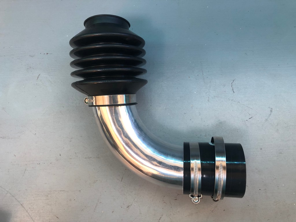
Bellows Hose. (Part Number: 595007)

This item took a bit more thought. It needed to be extendable and flexible; so spiral hose wouldn’t work. There are plenty of firms in China who could make what I needed for very little money but I’d have to buy them in bulk. Having 199 spare hoses seemed excessive!
Agricultural spares seemed a likely source but this yielded no practical results. There is a similar looking part on the air intake systems of some Jeeps… but I drew the line at that.
In the end Google came up with a caravan spares website. The bellows hoses were the right diameter, visually looked the right length, made in the UK and as cheap as chips. Trailer brake bellows protect the sliding shaft (part of the braking system) between the trailer hitch and the trailer chassis. They were sold as “ventilated” but I easily closed the tiny slices with some vulcanising solution.
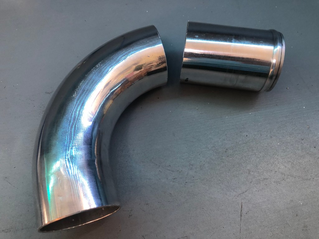
90 degree metal bend. (Part Number: 595005)

The 90 degree bend I got from Silicon Hoses in the UK is mandrel bent aluminium rather than 3 welded sections of the original Land Rover part. Fortunately, the latter is almost identical to the one that penetrates the bonnet (shown above) so I had something for comparison.
Obviously, the welded part has a much tighter bend making the system as compact as possible. But with the longer reach of the aluminium bend, I was able to place the bonnet penetration very close the bonnet hinge.
This gave two advantages. Firstly, the bellows hose wouldn’t have to extend as far when the bonnet was opened and secondly, the flexible hose (from the raised air intake to bonnet spigot) was visually better aligned.

Next a rough make was made on the end of the bend as a staring point to establish how much to trim off. Using a spirit level, a steel rule and the wing top as a datum, I can start to assess where to make the cut.
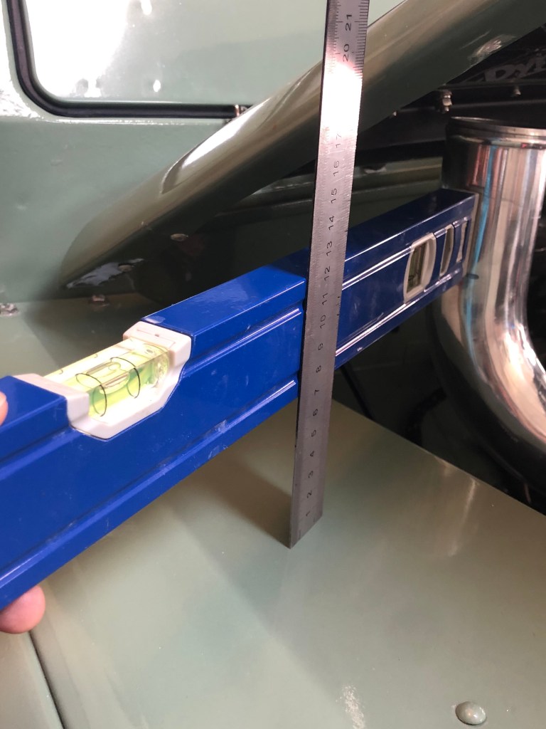


The mark I made on the tube is 70mm above datum. The top of bonnet 95mm above datum and the perpetration is 33mm. I need to move my line on the tube down 8mm. This calculation doesn’t take into account the thickness of the bonnet so 8mm should be perfectly OK and the spigot and bend won’t clash when the bonnet closes.


Next job was to start setting out where to cut the 65mm diameter hole in the bonnet. I didn’t want the spigot and bend to be off centre to each other. This wasn’t a job I could afford to get wrong… replacement bonnets are not off the self items these days.
If I could close the bonnet and some how draw a line around the edge of the bellows, that would give me the outside diameter of the hole but I’d need arms made of spaghetti or remove the engine.
In the end, the simplest solutions are always the neatest…


Knowing the diameter is 65mm, I used a pair of compasses to prescribe the centre of the painted circle and drilled a 5mm pilot hole from beneath.

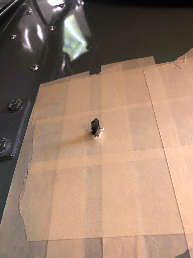


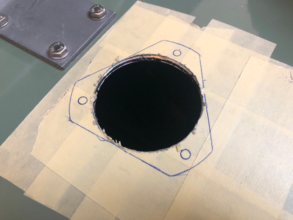
The hole was a little oversized as the guide drill in the centre of the hole cutter wasn’t exactly in the middle, so the cutter oscillated. The risk of trusting “precision” parts from DIY shops I guess.
