

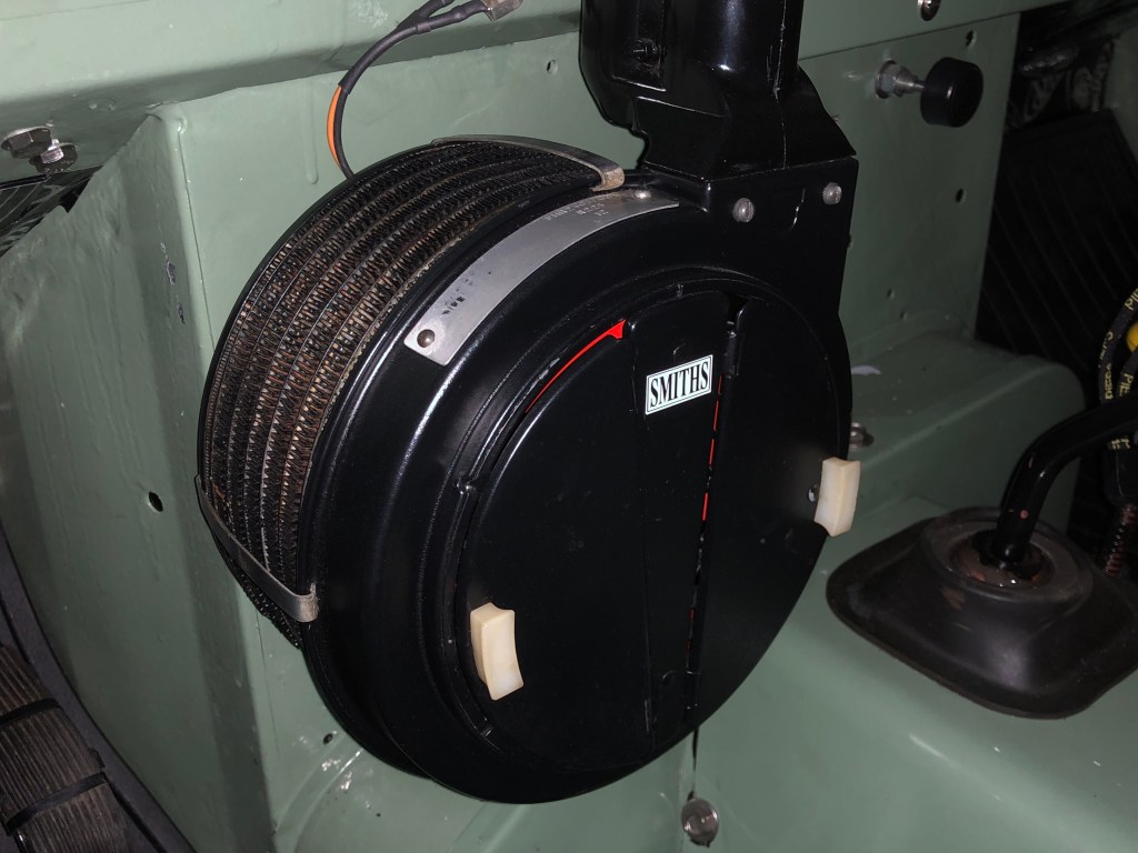
The original round Smiths heater keeps the inside of the Land Rover cosy on cold days… surprisingly so give its small size. The motor in mine has always been noisy. This is less surprising, given its age. One option would be to strip it down and replace the bearings and bushes but I’d end up with the heater on the bench waiting for parts for ages. Not ideal in the current weather. I found an new OEM Smiths motor on eBay for a reasonable price in the UK so I ordered and fitted one of those. I’ll keep the original motor for a rainy day project.
Exchanging the heater motor is pretty straightforward… disconnect the positive and negative cables, remove the face plate, remove the fan and the three mounting bolts and withdraw the motor. Install new motor. Simple… you’d have thought so anyway.
On on…


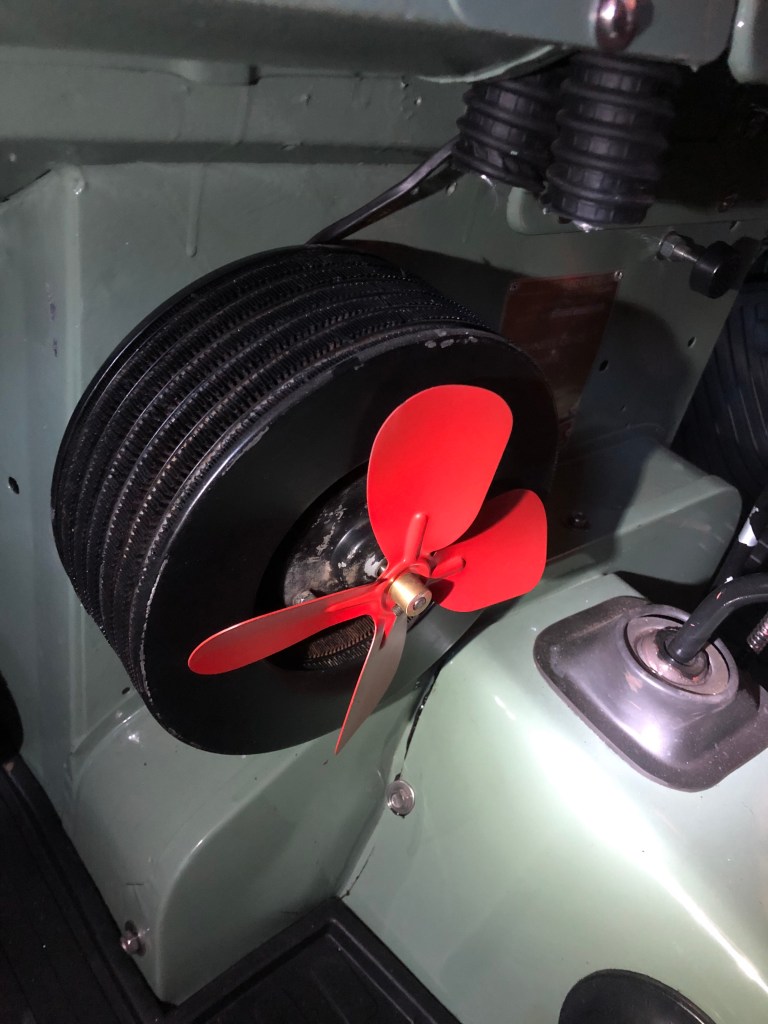
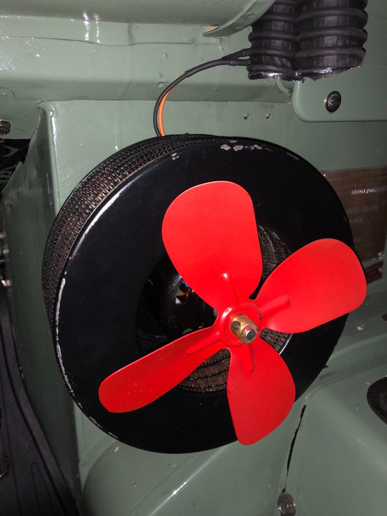
This is removed by unscrewing the small grub screw on the brass boss and sliding the fan off.

(Seen here fitted to the new motor)
Up until this point, I was a bit concerned that something wasn’t right. As soon as I unpacked the motor, I knew I was in for more work than planned but not sure what…

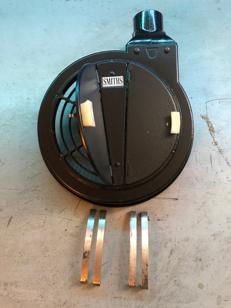
It’s not uncommon the motors to have a myriad of uses. I suspect the new motor on the left is for a Clayton heater. Very similar to a Smiths but slightly deeper. Some research proved me right. Clayton actually sell the same motor with the advise the shaft needs to be cut down.
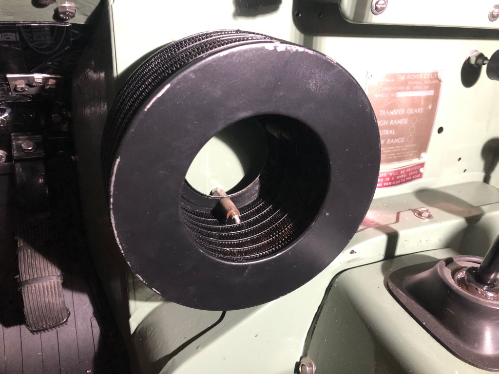
Fortunately, the three mounting posts that hold the motor can be adjusted to move the whole heater matrix fore and aft, thus allowing the longer motor to fit without touching the bulkhead behind.
I didn’t take any photos of adjusting the posts so we’ll move to the next problem.
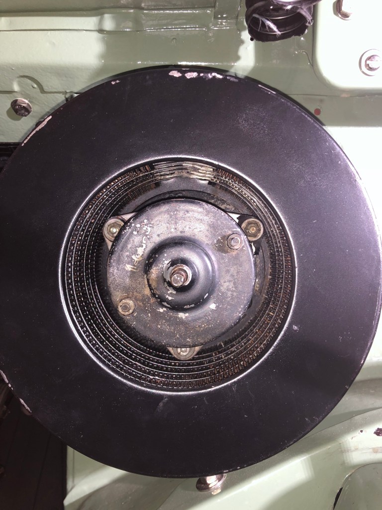
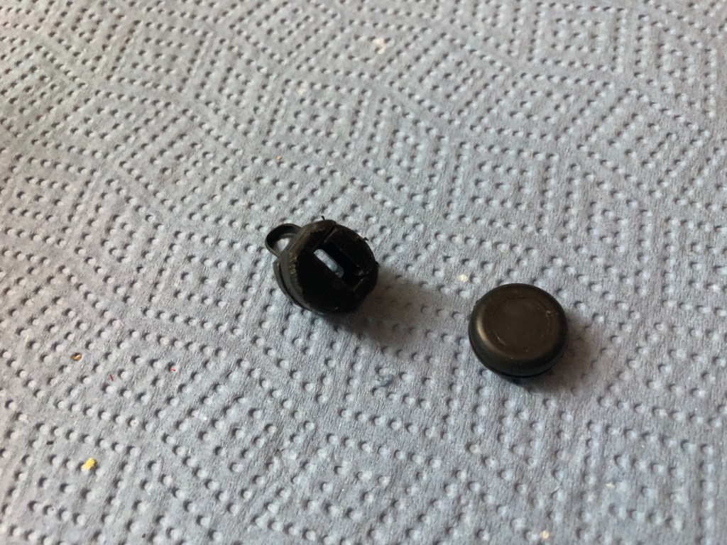
With the matrix in the right position, I was still unable to push the motor fully home on the posts. Something was getting in the way.
This was of such a size, if was fouling the back of the matrix.

Next I needed to establish how much to cut down the shaft. Using the mounting flange as a reference point, I measured the distance from the flange to the end of the shaft on the old and now motors.
The difference between the two figures would be the amount to be cut off. It was really hard to hold the motor vertically, user the callipers and take a photo of the whole thing so the following will have to do.


(In general my thumb nails are not this grubby)
Therefore, the shaft on the new motor needed to be trimmed down by 13mm…

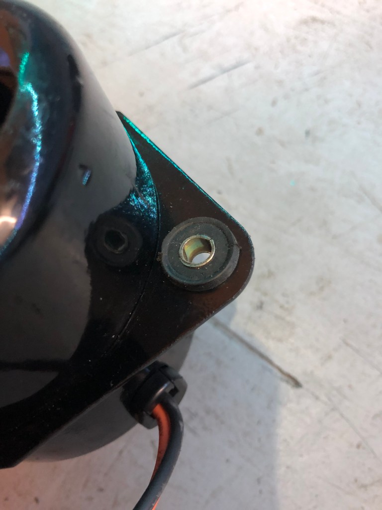
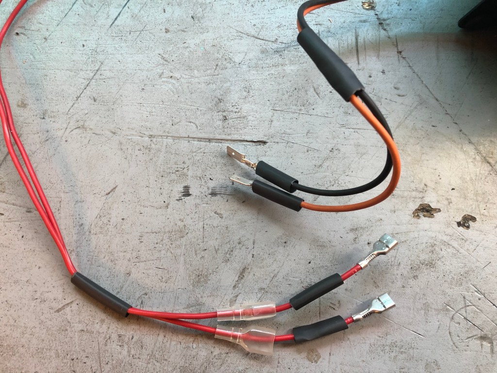
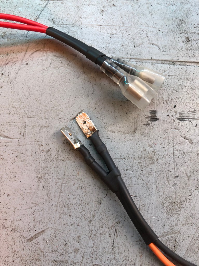
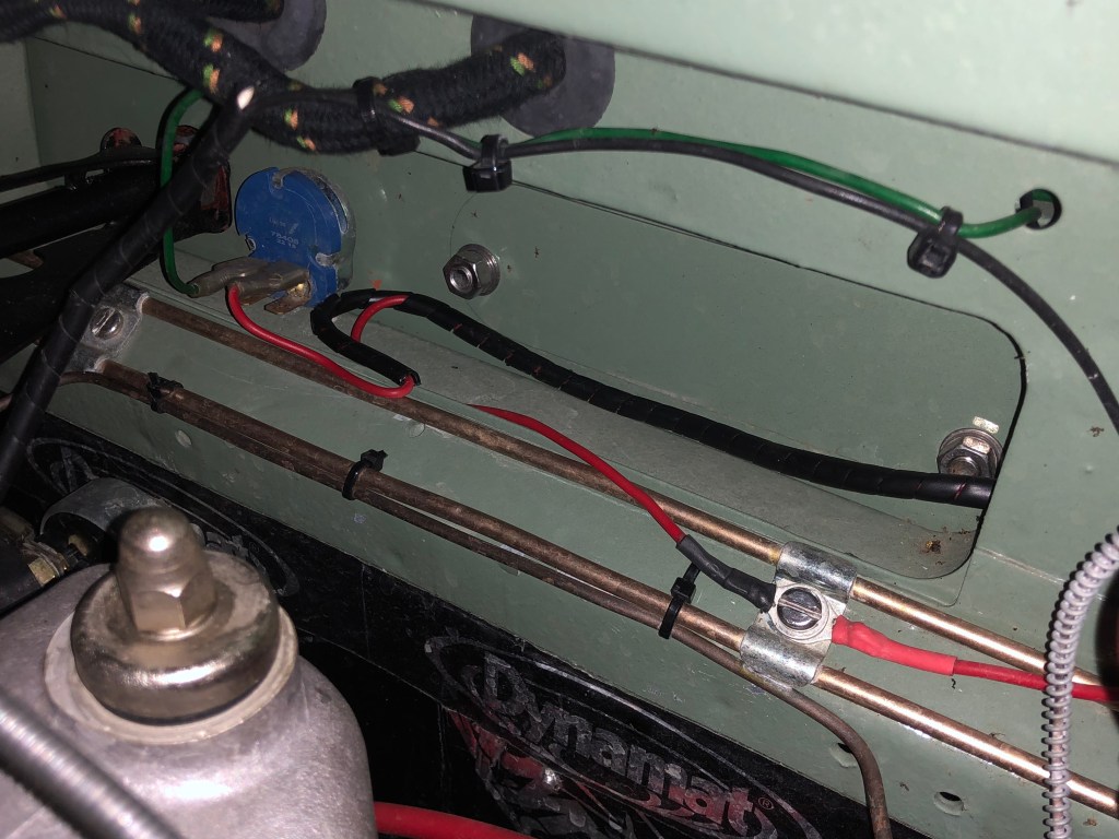
With the motor now able to fit into the matrix without fouling anything and the shaft the correct length, the wiring needed to be extended.

The round eye fixing is the earth post and the push fit connector fits on the rheostat.
Now everything can be put back together again.

Note of caution; be very gentle with the grub screw. It’s made of steel and the boss is made of brass. It doesn’t require a lot of force to strip the thread.
I used a short length of cable wrap to tidy things up.
All in all, it was perhaps a bit more work than expected but the motor is a lot quieter. Unfortunately the rheostat (the rotating switch used to regulate the speed of the motor) refuses to work as intended so that needs to be replaced, but this is a very quick and inexpensive swap.

Great to see you are still going. Love your work, it’s been really helpful to me. Thank you.
LikeLiked by 1 person
Hi, Do you have PN/Source for the little rubber motor mounts? Cheers!
LikeLike